DIY Layout Creator
Introduction
DIY Layout Creator (DIYLC) is a specialized software tool designed for hobbyists and electronics enthusiasts to create circuit layouts on stripboard, perfboard, PCB, and point-to-point wiring. It provides an intuitive, drag-and-drop interface for placing components, arranging connections, and visualizing circuit designs before assembly. With a built-in component library and customization options, it allows users to design layouts with precision and clarity. The software is particularly useful for designing, analyzing, and debugging guitar wiring diagrams, helping musicians and builders plan and troubleshoot custom wiring configurations for pickups, switches, and controls. Its versatility makes it an ideal solution for DIY electronics projects, prototyping, and documentation.
Project Examples
Point-to-point tube amplifier

Guitar wiring

PCB tube amplifier

Perfboard guitar effect

5-Minute Quick Start & Shortcut Cheat Sheet
1. System Requirements & Installation Quick-Check
DIYLC runs cross-platform on Windows, macOS, and Linux. The current release is built on Java 21 LTS.
Installation by Operating System
- Windows (64-bit):
- Download diylc-6.x.x-win64.exe (Installer) or diylc-6.x.x-win64.zip.
- Includes bundled Java JRE. If Windows Defender flags the file, click More Info → Run Anyway.
- macOS (Intel & Apple Silicon):
- Download diylc-6.x.x-osx-silicon.zip (M-series) or diylc-6.x.x-osx-intel.zip.
- Extract and drag DIYLC.app to your Applications folder.
- If macOS blocks launch, navigate to System Settings > Privacy & Security and select Open Anyway.
- Linux (64-bit):
- Download diylc-6.x.x-linux.zip, extract, and double-click the executable AppImage.
- Universal Package (All Platforms):
- Requires Java 21+ installed (java -version).
- Run via run.bat (Windows) or run.sh (macOS/Linux).
2. Interface Overview
- Component Library (Left Drawer): Browse components grouped by category (Boards, Passive, Semiconductors, Guitar, Tubes, Schematics, Shapes).
- Canvas (Center Area): The grid-based work region with adjustable rulers (mm/inches) and zoom controls.
- Properties & Layer Tree (Right Panel): Displays properties of selected components and Z-order layer management.
- AI Assistant (Right Drawer): In-app chat for troubleshooting, design tips, and circuit questions.
3. Essential Key Commands & Controls
- Q: Jump to search the component tree.
- ~ (Tilde): Repeat and place another instance of the previously created component.
- Ctrl / Cmd + D: Duplicate selected component(s).
- Ctrl / Cmd + E: Edit selected component properties (value, package, color, etc.).
- Alt / Option + Left / Right Arrow: Rotate selected component(s) counter-clockwise or clockwise.
- Arrow Keys: Nudge selected component by one grid increment.
- Shift + Arrow Keys: Nudge selected component by one pixel for precision alignment.
- Shift (while dragging): Lock movement along a single axis (horizontal or vertical).
- Ctrl (while dragging): Temporarily toggle Sticky Points to prevent unwanted snapping.
- Ctrl / Cmd + G / Ctrl / Cmd + U: Group or ungroup selected components.
- Ctrl / Cmd + 1 – 6: Toggle visibility of layers (Chassis, Board, Trace, Component, Wiring, Text).
- Ctrl / Cmd + F: Find a component by name, select it, and pan to it on canvas.
4. Key Workflows & Features
Creating a Layout
- Place a Board: Drag a Veroboard, Perfboard, or PCB shape from the Boards category onto the canvas.
- Add Components: Drag resistors, capacitors, transistors, or ICs onto board holes/pads.
- Route Connections & Wires: Use the Connectivity menu to add flexible wires, jumpers, trace cuts, or ground busses.
Analysis & Debugging Tools (Analyze Menu)
- Guitar Wiring Analyzer: Verifies switch matrix combinations, coil splits, phase relationships, and hum-canceling positions.
- Virtual Multimeter: Graphically traces electrical paths between two points as series/parallel sub-circuits.
- Compare With…: Compares two layouts or schematics to check if they are electronically equivalent.
- Highlight Connected Areas: Click any point/node to highlight all connected paths on the board.
5. Exporting & Sharing Your Work
- Image / PDF Export: Go to File > Export Image/PDF for high-resolution documentation.
- Bill of Materials (BOM): Go to File > Export BOM to generate a complete list of required parts and quantities.
- Gerber PCB Fabrication: Go to File > Export Gerber to generate manufacturing files for PCB fabricators.
- DIYLC Cloud Integration: Use the Cloud menu to search, download, and publish community layouts.
6. Keeping DIYLC Updated
- Look for the glowing lightbulb icon in the bottom-right corner of the status bar when an update is available.
- Official download channels: GitHub Releases and Patreon.
- Mac users: in most instances, the Gatekeeper will block DIYLC and mark it as damaged because it’s a 3rd party app from an independent vendor (me). This document covers how to allow DIYLC on your Mac. Alternatively, all Patreon supporters get access to an Apple-notarized version of DIYLC that is hassle free.
- GitHub Release Page – get the latest version for all platforms.
- GitHub Wiki Pages – to access user documentation as well as developer documentation.
- GitHub Issues Page – to request a feature or report an issue or bug.
- Patreon – support further development and get access to exclusive content, AI credits and hassle-free Mac builds.
- Cloud Project Browser – to browse, search and download community .DIY files.
- Discussion Group – for any questions of DIYLC-related discussion with the wider community.
- 🆓 Free for Life: A true old-school offline app—the app you download is yours forever and the files you created are yours.
- 💻 Platform Independence: Runs locally on any machine capable of running Java JRE/JDK 21 or newer.
- 🖱️ Intuitive UI: Easy-to-use interface; most operations can be done seamlessly with a mouse.
- 🎛️ Versatile Designs: Draw PCB, perfboard, stripboard, or point-to-point layouts, schematics, guitar wiring diagrams or custom faceplates.
- 🔌 Highly Extensible: API allows custom plug-ins and new components to be added easily.
- 🚀 Optimized: Improved performance and reduced memory consumption.
- 💾 Smart Defaults: Save default values individually for each component property.
- 🖨️ Export Options: Export outputs to image, PDF, or printer.
- 📄 Toner Transfer & Gerber: Export PCB trace masks for toner transfer or Gerber files for fabrication.
- 📋 Bill of Materials: Create a BOM within the project or export to multiple file formats.
- 🔍 Guitar Wiring Analysis: Analyze guitar wirings and visualize detailed pickup configurations for each switch state.
- ☁️ Cloud Integration: Share your projects, search the cloud, and download other users’ designs.
- 🤖 AI Powered: Features a built-in AI assistant to help answer general electronics questions, guide you through DIYLC’s usability, and provide insights or troubleshooting for the specific circuit you are designing.
- ⚡ Circuit Analysis: Various tools aimed to help you debug and analyze your circuits.
- 📈 SPICE Netlists: Export circuits directly to SPICE-compatible netlists.
- Version 1 (2006): Written in Delphi for Windows. It was tailored strictly to guitar pedal circuit boards (vero, perfboard, and simple PCBs) and instantly replaced generic graphics software within the pedal-building community.
- Version 2 (2008): Rewritten in Java to enable cross-platform functionality and introduced an XML-based component format. While it expanded into schematic and chassis wiring diagrams, defining components as purely visual primitive shapes limited custom behavior, impacted performance, and lacked backwards compatibility with Version 1 files.
- Version 3 (2011): Completely rewritten from scratch, made open-source, and redesigned with a modular “component-as-code” architecture. It introduced full backwards compatibility, vacuum tube and guitar wiring component libraries, and DIYLC Cloud for sharing layouts.
- Version 4 (2020): Modernized on Java 8, introducing initial circuit analysis and debugging features that turned DIYLC into an interactive design assistant.
- Version 5 (2025): Upgraded to Java 17 and Maven, introducing built-in AI tools (AI Assistant and AI Analyzer) and Apple-notarized macOS distributions.
- Version 6 (2026): Adopted Java 21 to enhance runtime efficiency, memory management, and overall system performance, solidifying a stable foundation for ongoing AI-assisted design features. Expanding to modern DIY projects including SBC’s, displays, sensors, etc.
- Become a Patreon.
- Make a one-time donation with PayPal.
- Help with adding the information to the user manual or other project documentation.
- Extend the component base, read this wiki to learn how to create new components.
- Add a new functionality though plug-ins, read this wiki to learn how to create new plug-ins.
- Big thanks goes to folks from the following online communities for contributing ideas and helped test the app: DIY Stompboxes, AX84 and Free Stompboxes.
- I’m happy to report that DIYLC 4 is the fastest version ever. YourKit Java Profiler helped tremendously with memory and performance profiling and pointed me to places in the code that took longer to run or consumed more memory than I’d like them to. I strongly recommend this tool to anyone developing Java or .NET applications because it helps finding bottlenecks and allocation hot-spots very fast.
YourKit is kindly supporting open source projects with its full-featured Java Profiler.
YourKit, LLC is the creator of innovative and intelligent tools for profiling Java and .NET applications.
Take a look at YourKit’s leading software products: YourKit Java Profiler and YourKit .NET Profiler
7. Useful Links
Features
The 20-Year Story & Vision
The Origins (2006)
DIY Layout Creator began in 2006 with a post by Branislav Stojković (bancika) on the DIY Stompboxes forum. At the time, pedal builders relied on generic graphics applications like MS Paint or Visio, tediously copy-pasting components from hand-drawn templates to map out stripboard and perfboard layouts. DIYLC was envisioned as a free, dedicated tool designed by a builder specifically for fellow makers.
Evolutionary History
Project Vision
DIYLC is maintained primarily by a single developer but remains deeply rooted in the open-source DIY maker community. Unlike complex professional EDA suites (e.g., KiCAD or Eagle), DIYLC’s core philosophy is to remain focused, fast, and accessible. It prioritizes real-world, practical DIY workflows—such as point-to-point wiring, board layouts, and wiring diagrams—making the design and documentation process clear and enjoyable.
Master DIY Layout Creator and streamline your design workflow!
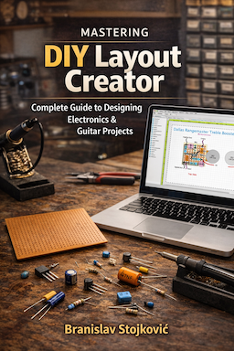 |
The Official DIYLC Guide (v1.0) is a comprehensive 174-page eBook that goes way beyond the basics. It features step-by-step design workflows for everything from multi-layer PCBs to hot-rodded point-to-point tube amps. Learn to master advanced tools like the Virtual Multimeter, Netlist generation, the Guitar Wiring Analyzer, and the new AI Assistant. Click here to grab your copy! Buying v1.0 guarantees you free lifetime updates as the app evolves. Active Patreon supporters get an additional 50% off or a completely free copy. Check the Patreon feed for your VIP link! |
Want to contribute?
DIYLC is provided free of charge and can be used and redistributed freely. Please note that it takes a lot of time and effort to build, test and maintain it and to interact with the growing community of users. If you find DIYLC useful and want to support further development, these are some of the ways you can contribute
License information
Source code is released under GNU General Public License version 3. Contact the project owner to obtain a license in case you plan to use the source code, or any part of it, in commercial purposes.
![Lost Without You - John Petrucci [Guitar Cover]](https://i.ytimg.com/vi/CvhLPmLvHVM/default.jpg "Lost Without You - John Petrucci [Guitar Cover]")



I have your Layout designer on my PC (which is at work). I have converted all my computers over to the MAC. When I tried to load your V3 on my MAC, it says it is for Windows. Do you have a MAC version. I love your simple, yet complex, program. I made a decent donation after having such success on my PC. I would make an even larger donation if I could get the program to run on my MAC here at home.
Thanks
v3 will run on mac, just unpack the archive, open the terminal, change the directory to diylc3 (cd) and type ./run.sh
Cheers
Hello Bancika,
I tried to change the directory to diylc3 and terminal said “no such directory” I unpacked the archive and terminal did not find it. Can you please tell me if I am doing something wrong?
Thanks!
it doesn’t create diylc3 automatically, extracts everything wherever you extracted the archive. You can create a folder named like that and extract the archive there
Cheers
Hi,
I worked with DIYLC v3 for a while on my Linux machine, then had to switch back to v1 because v3 has some features that are very annoying.
First, let me tell you that the v3 is a very nice piece of software, with many options and is also much faster. My intent with this post is to give my “contribution”, not to destroy your (very good) job.
V1 is wonderful: very very very easy to use, minimal (that’s what we should expect), clear. Sure it had to be speeded up a bit, because some things really took too long. But that way… was the right way.
In V3 i think you lost the focus on what DIYLC was (is) loved for: easy to use. V3 is messed up with graphics, nice looking resistors, caps etc… but… they stretch when we resize them (?!?!). V1 didn’t do that, a resistor has “standard” size and that size remains even if the resistor spans over 7 holes. Was it really necessary to give the ability to set component size by hand? Why not giving standard sizes (as it was on V1) maybe depending on voltage/power rating? Specifiying sizes by hand should be made a customization, rather than the standard? e.g. resistors:
blue–>1%, beige–>5%,
1/4W, 1/2W –> fixed size: 8mm x 2 mm
1W –> …
5W –> …
+ “Use custom size” –> if checked the user inserts the size he wants to use.
When printing a vero with V3… how can we know a component name/value if it is vertical? e.g. resistor that spans 2 holes. While soldering, V1 output was way easier to read/follow … don’t you think?
What is missing is a nice connectivity checker. Something easy that highlights the path connected to the hole you wich to check.
What is way better in v3: selection/moving tools, speed, choose component by existing type names (e.g. DPDT, 3PDT etc…), cables as editable splines,
Thank you!
Andrea
Hey
I’ve been using v.1 and when I load my projects into v.3 they won’t print to correct size.
Is this because I’m going from v.1 to v.3 or is it something I am overlooking?
I am really loving the new version , if only I could figure this out.
thanks
Chris
Hi Bancika. Amazing job about the DIY Layout. I found a bug it´s quite anoying but at same time I found a solution, sometimes for no reason some parts are blocked and is impossible to select. Doesn´t matter if the block selects are unchecked. The solution is to go to the Edit Panel and make a “Select all”. I saw that one of your task list is to make a submini amp, and I want to know if you have the socket component drawing, because I was doing by hand but is really hard to do in that way.
Hey,
Can you make it so that it opens the 2.x files?
Thanks,
Owen
that will be supported
Hi Bancika,
I’ve been working on a board with beta version 3.0.6. When I try opening my saved file with version 3.0.8 the layout looks squished. I think the components are all placed closer together in the new version. Originally the board was 3″ high, now it is more like 2.25″. Is there anyway to preserve the layout in the new version, or do I need to keep using 3.0.6 beta for the rest of this project? Thanks!
David
Hi,
I have increased screen resolution between 3.0.6 and 3.0.7 to allow more details. The problem is that versions up to 3.0.7 store coordinates as pixels, so resolution increase made everything squishy when opened in the new one. This shouldn’t happen with layouts made in newer versions because I’m storing everything in inches since 3.0.8. One way to fix it would be to open the file in notepad and update coordinates (XML nodes named x and y) manually bu multiplying them with 200/96=2.08333
I could make you a small util that does it, but probably not before Monday.
Sorry for inconvenience 🙁
Cheers,
Bane
I don’t know anything about XML, but I can probably write a perl script to munch a text file and scale the coordinates without too much trouble. Thanks explaining the work-around.
From my part I’m not able to use the new version seems the program response is very very slow on my PC
AMD Atlon 64 X2 dual – processor 6000+ – 3 GHz – 2 GB ram
however I would like you give the program a feature that I used in Autocad
the ability to load an image as background so is very easy to put a .jpg or .bmp with a layout and to redraw it in few time
Kagliostro
It should run smooth on your machine. My laptop is 2GHz dual core and it runs smoothly. What kind of OS are you using and what java?
You can load an image, just go to Misc tab in the toolbox.
Cheers
i would like to see something like this combined with synthedit or synthmaker and an inbuilt graphic package in the creation of vst instruments and dll files , so i could use the schematics layouts see in old synthesizer manuals and make the whole thing a lot easier to understand..
I’m using your diylc v3 for turret board layout and it’s a great help. Not as quirky as v2. Thanks so much for providing this very useful software. Keep up the good work.
Hi, i just downloaded DIYLC 3.06 from diylc site… But the executable inside is 3.05, and more, a get very few components on the component bar (only main.jar in the library dir)… Am i doing something wrong ? (no tube socket, for example, nor enclosures from version 2).. thanks in advance.. anyway, very cool
this has been resolved in 3.0.7
Cheers
@Bancika:
Been a longtime user of V2 and it has served me well. Aside from performance issues it suited my needs almost perfectly…
Just tried V3 beta and am very impressed with how quick and responsive it is, it has almost all of the old features I’m used to and more. I’d just like to add a couple of suggestions to the list:
– When doing stripboard layouts in V2 I found having the board holes numbered across the top very useful – I tend to think in holes rather than cm/in as I know how may holes/rows will fit comfortably into a given enclosure. Would be nice to have that option again.
– Rotary switches. I can see that this may be tricky to implement, but would be nice. It is still easy enough to use the regular switches to stand in for rotaries, but requires some extra annotation (especially if you want to post your layout online) .
Anyway, this all sounds too much like nitpicking already, and I should really just say thanks for this great bit of development.
@Axel I think this software is great (on Ubuntu), but it is a bit too slow for me, although it speeds up a bit if you remove the stripboard.
Thanks for the tip about Sun Java, I tried to download and install Java from the Oracle website, but DIYLC wouldn’t run. Have you any useful hints – is there a pointer missing to the Java interpreter or something?
I have had a quick look at V3 – this is also slow, but ok if you remove the stripboard!
V3 should be much quicker than V2. I’m running a test with a perf board across half the screen and 128 capacitors scattered across the screen and it’s fast enough. And that’s on the laptop.
Cheers
What about power supplies at least give us a battery clip where we can edit the voltages
Great piece of software!
For those who experience speed problem when running under Linux, I have found out that DiyLC runs faster with Sun Java than with OpenJDK… I tested on several machines and with Sun, DiyLC runs as fast as under windows…
Also, under Linux, the component library doesn’t appear unless you start DiyLC with the command:
java -jar DIYLC.jar -javaagent:jarpath=lib/
Cheers
Having problems running .. Installed 1x and got error message “no data set” and “no active doccument”.. Running Vista Home Premium 64bit.. is that the problem? Version 2x just froze when I opened it :(..
Thanks… Dave
Just get into folder and set the compatibility mode for Win XP and thats all.
i’ve just opened the diy layout creator beta 2, and the first things that come to my mind is : i’ve got to get close to my screen, to see what’s written ( project, settings, etc, tools … ) i’d love this to be editable, to have bigger letters, and i think i liked the first version of the soft, for the presentation, but i just wished some different evolutions than this one, although , it might be cool too, i didn’t test it really yet.
and really, the most cool feature, unique among all these pcb software, please add the ability to insert some jpegs, just like in photoshop. a layer, then some magnetic points that i’d place myself , from this layer, and then the components would hook onto these points, the way i’d want. this would be so cool.
Cause imagine, if you have a scan of an old pcb, you have the traces, the dimensions of the original board, and you’d like to make a presentation, adding these symbolic components that you have, to make some corrections, and communicate this between diyers you know. you’d see the traces by transparency, and the components on the top. different layers. and the transparency /opacity of the different layers could be aditable.
really also the zoom. too static. more like into photoshop.
yeah, and white components, on a black screen, instad of on a white screen , just an option added.
but i love the principle for all the rest, keep this the way it is ! ; )
so fast : having a board , a circuit, click and drag some components, some connections, and the feeling that you’re quite free, simple, best.
I really hope to see such evolutions, if you think you can, and want to do it. i’d use only this soft then.
thanks again,
Adrien
Hi !
Well, diy layout creator is the best soft, very simple, an dit looks like a real board. I love it. But, please, may I ask you if you could perhaps add some other features ?
I’d be very interested to have a zoom in an out included ( some are more comfortable than some others. Maybe photoshop like, maybe shortcut with it too, to have the choice, maybe a slide , maybe a shortcut and a move of the mouse … you know … )
AND, the possibility to insert some jpegs, witth a scale somewhere, so that, I could insert some vintage pcb drawings, in black and white, synchronised with a rule , visible in the working area, ( the picture would be scaled previously at the 1/1 scale, into photoshop for example, then inserted at scale one, into diy layout creator , see what I mean ? ) , in the background, and editable a little bit.
Then, pure pleasure to add these components, moding them etc …
And about the points of the pcb inserted, than won’t fit the diy layout creator orthogonal frame, well, then a simple feature would be cool : adding the magnetised points by ourself, following the pcb inserted in jpeg. Then the components would be added, and would recognize these points.
I hope that you’re reading me, and I’d be glad to discuss about it with you.
This would make this layout creator the absolute ultimate layout creator for effects. ( by the way, the old plexi amps, or fender amps, would be glad to have some boards that would look the way they are : just one more cool feature that could be added I think. ).
I know that sometimes, echoes from the public can stimulate the ideas, and make the soft to evolve in a cool way.
Oh, another cool feature would be to have a negative visual stuff , you know, instead of black on white, white on black, so it doesn’t hurt the eyes.
My screen , in my room, is a 2 meters wide screen, from a full hd videoprojector. Lot of light ; )
I hope that you noted all my requests, for all these features I’d love to see into this software.
One more : a feature that would allow the user to create , or import his own components drawing, from dwg or dxf, or even from some psd ( photoshop ) layers, or png or I don’t know .
The other way would be to add every components into photoshop, onto my pcb drawing, with it’s traces ( seen with a transparency, from the components side )
All the best, and thanks for this cool software.
Adrien
Great software Bancika,
I do have a couple of small suggestions.
*I would like to be able to rotate the schematic valve symbols.
*I notice when I “ctrl Z” it resets the page size to default.
*I am unable to change page size in “Page Edit”
*Is it possible to edit the symbols or create your own?
Thanks for taking the time to write this software. Paul is right This is neither too complex nor too crude.
Thanks for comments. I’ll include them in the new version. And yes, you can create your own symbols. Library contains XML files that define symbols. Start with the one that’s close to what you need, copy it and customize.
Cheers
Please add a breadboard layout, a way to cut a range of traces [instead of 1 at a time], jumper a range of holes [likewise], and a way to always skip the “non-standard IC size” message. Great program – thanks!
please update your layout collection of files !!!!!!!!!!!!!!!!!!! and where I send a circuit with version 1.x?
layout collection is for version 1.x, there’s no official collection for 2.x
I can include your circuits if you send them to stormbringer [at] mail.com
cheers
I think I am going to be using this, as all the other packages I have looked at are either too complex, too crude, won’t do stripboards or won’t run properly on Linux! That said, I hope you will welcome a couple of constructive comments in order of importance:
-There is no check that you have saved before exiting.
-If I open another package DIYLC disappears.
-It’s a bit slow – I assume that is just because it’s Java.
-The ‘check for update’ and ‘update library’ options result in a Java.io.ioexception error.
I have more – I can put them on here or you can email me if you prefer.
thanks for comments Paul. I know that it has many annoyances and version 3 is on its way. Unfortunately, it goes very slowly as I don’t have much time. Feel free to post your comments here, I’ll take them into account when making the new one.
Cheers
@Bancika: OK, more comments then!
If you are not used to this sort of software it might not occur to you to lock the circuit board layer, perhaps ‘locked’ should be the default. The locking doesn’t work reliably. It’s possible to put a circuit board underneath the ruler.
The speed is the biggest problem, it can get so slow that you get confused about what you have clicked and what you are waiting for. My 1.7GHz PC is fast enough for everything else I do.
Some more ‘Likes’
Easy to use.
Easy to add to library by editing XML of a similar component.
Good graphics.
Can show the enclosure to keep a check on size and position of off-board components.