DIY Sustainer
Introduction
Sustainer is a cool little device originally designed by Fernandes®. The kit contains a sustainer driver which replaces neck pickup on guitar and a circuit board that contains the electronics. The original Fernandes sustainer also has an active pickup which can be used as a conventional neck pickup when sustainer is not used, but this project does not include that feature. This limits guitar tonal options in one way but gives completely new possibilities.
Here’s how it works. When sustainer is turned on, we take the signal from the bridge pickup, amplify it using a simple audio amplifier and use the amplified signal to drive the driver instead of a regular guitar speaker. Think of the driver as speaker coil that cannot move. The driver generates electromagnetic (EM) field that moves the strings instead of moving the conventional speaker diaphragm. Guitar strings are close to the driver and get excited by the EM field, casing them to vibrate indefinitely. In a nutshell, sustainer works exactly the opposite from a regular guitar pickup. Instead of picking up the vibrations of the strings, it is causing the strings to vibrate.
Keep in mind though, that we cannot use a conventional guitar pickup as a driver because it has very high impedance and DC resistance (typically 5K-20K). Amplifiers usually work with loads between 4 and 8 ohms, so we will need to make our driver very similar to guitar pickup, but wind it with thicker wire and less turns to aim for DC resistance of 8 ohms.
Building your own sustainer is not simple and requires a lot of research and experimenting. Make sure you have basic knowledge in soldering, electronics, guitar wiring and pickup building. Otherwise, this can easily prove to be a painful project and you may be better off buying a real Ferndandes sustainer or Sustainiac.

This photo shows Fernandes Sustainer kit which is cool but very expensive (above 200$). Fortunately, great guys from Project Guitar Forum (most of all Pete/psw and Col) developed DIY friendly project that costs much less than original but still sounds good. Total cost of the build is between 10 and 20 euros (or dollars), depending on what you already have. Also, I’d like to thank PSW Pete for sending me a spool of 0.2mm wire all the way from Australia at no cost.
Step 1: getting a bobbin
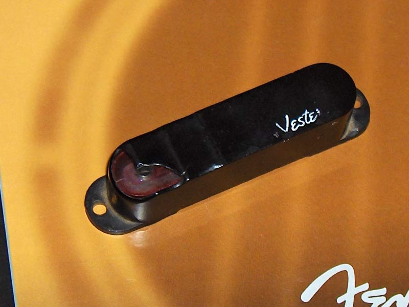
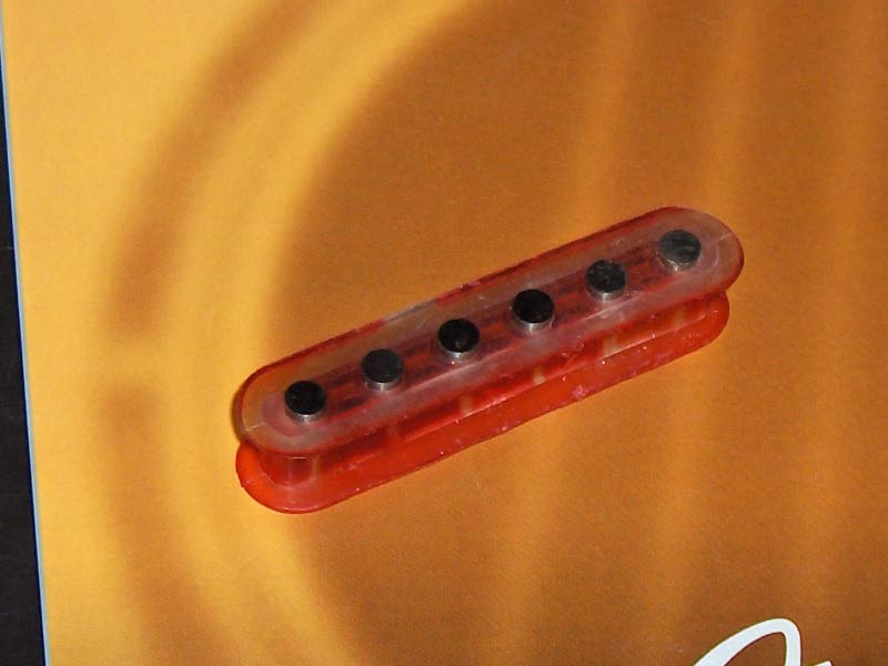
You can buy a new single coil bobbin and pickup cover online or try to salvage one from an old pickup. I got a bunch of them from a friend and picked one that had a bobbin I liked. I used a traditional single coil bobbin with 6 pole pieces which makes for a discrete driver, but many DIY-ers had great results with rail-type pickups, and original sustainer is also rail.
Strip the pickup and remove all wire. There’s a lot of very thin wire there so cutting it instead of unwinding is the way to go. In this case, pickup was potted which made stripping wire even harder. Nice thing about this is that pole pieces can be adjusted, so if I end up with uneven sustain I’ll be able to set poles higher or lower to compensate difference.
Step 2: modifying the bobbin height
Pickup coils are usually wound to around 10mm of height and bobbins are designed to fit a coil that’s 10mm high. For sustainer driver, optimal coil height seems to be around 3mm, which means that we need to modify the bobbin to limit coil height to 3mm. One way to do it is shown below.
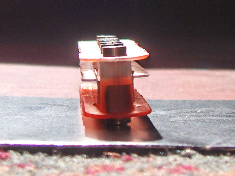
The way I did it was using a thin (around 0.5mm) piece of transparent plastic used for packaging that I bent into L profile and cut to shape with scissors. Then I glued it in place using epoxy glue. Super glue can also be used for quicker setting time.
Step 3: winding the coil
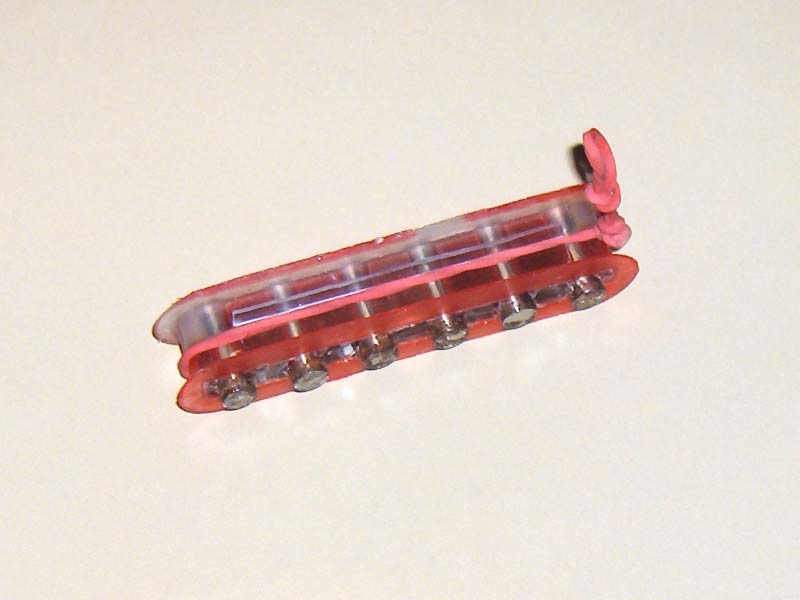
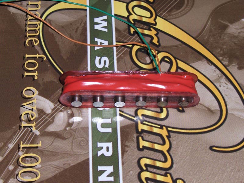
The recommended wire gauge for winding the coil is 0.2mm (AWG #32). Other gauges might work, but thinner wire will have less resistance, so it would take less turns to get to the target coil resistance of 8 ohms. With less turns we’ll have lower inductance, so our driver will be weaker. Other other hand, thicker wire has less resistance, so we need more turns to get to 8 ohms. More turns of thicker wire would make a physically large coil that might be too large to fit on a guitar pickup bobbin. 0.2mm is a good middle ground between physical size and number of turns needed to produce a coil with DC resistance of 8 ohms. Taking the resistance of copper into account, we can calculate that we need around 14.9m of wire to get the coil to target resistance of around 8 ohms. Using the calculator for estimating number of turns we get around 120 turns on a strat bobbin. It will depend on the geometry of the bobbin, so it’s best to check coil resistance as you go. I used transparent universal glue to pot the pickup after each 20 or so turns to make sure the coil is kept in place and to prevent microphonics.
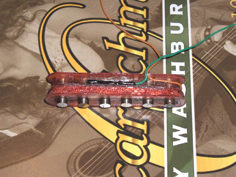
After 100 or so turns you can try to take the insulation off a tiny portion of the wire using a knife and measure the resistance of the coil so far. If you reached 8ohm, it’s done. Otherwise, do a layer or two more and repeat until you get to the target resistance. When it’s done, I soldered leads to both ends of the coil, secured them with a blob of glue and covered everything with insulating tape.
Step 4: the circuit
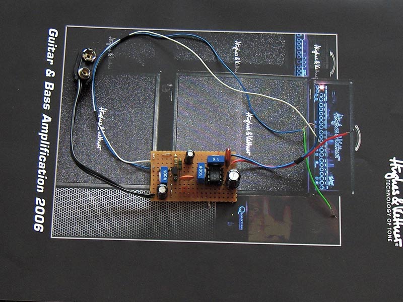
For the circuit we want to build a real clean guitar amplifier that operates the same way as a conventional amplifier, but instead of driving a speaker, it drives our sustainer. Pretty much any amplifier that can deliver few hundreds of milliwatts of power can do the job. A few people have reported Fetzer/Ruby amplifier from ROG to be performing well, so I decided to use that circuit. It’s got one FET gain stage (Fetzer Valve booster) that amplifies input signal before it hits the LM386 power amplifier taken from Ruby amplifier circuit. Both circuits may be found at runoffgroove.com and it’s just a matter of putting them together. I used trimmers for all controls and omitted Ruby volume control, as we already have one in the Fetzer Valve part of the circuit. 100K bias trimmer on the FET should be set to position that gives us roughly 4.5V at the drain of the FET and the remaining two trimmers should be adjusted at the end when the driver is installed in the guitar.

For my build I used this simple but not very compact perfboard layout. I suggest building as small board as possible, increasing the chance of fitting it inside the guitar without the need for routing.
Step 5: wiring
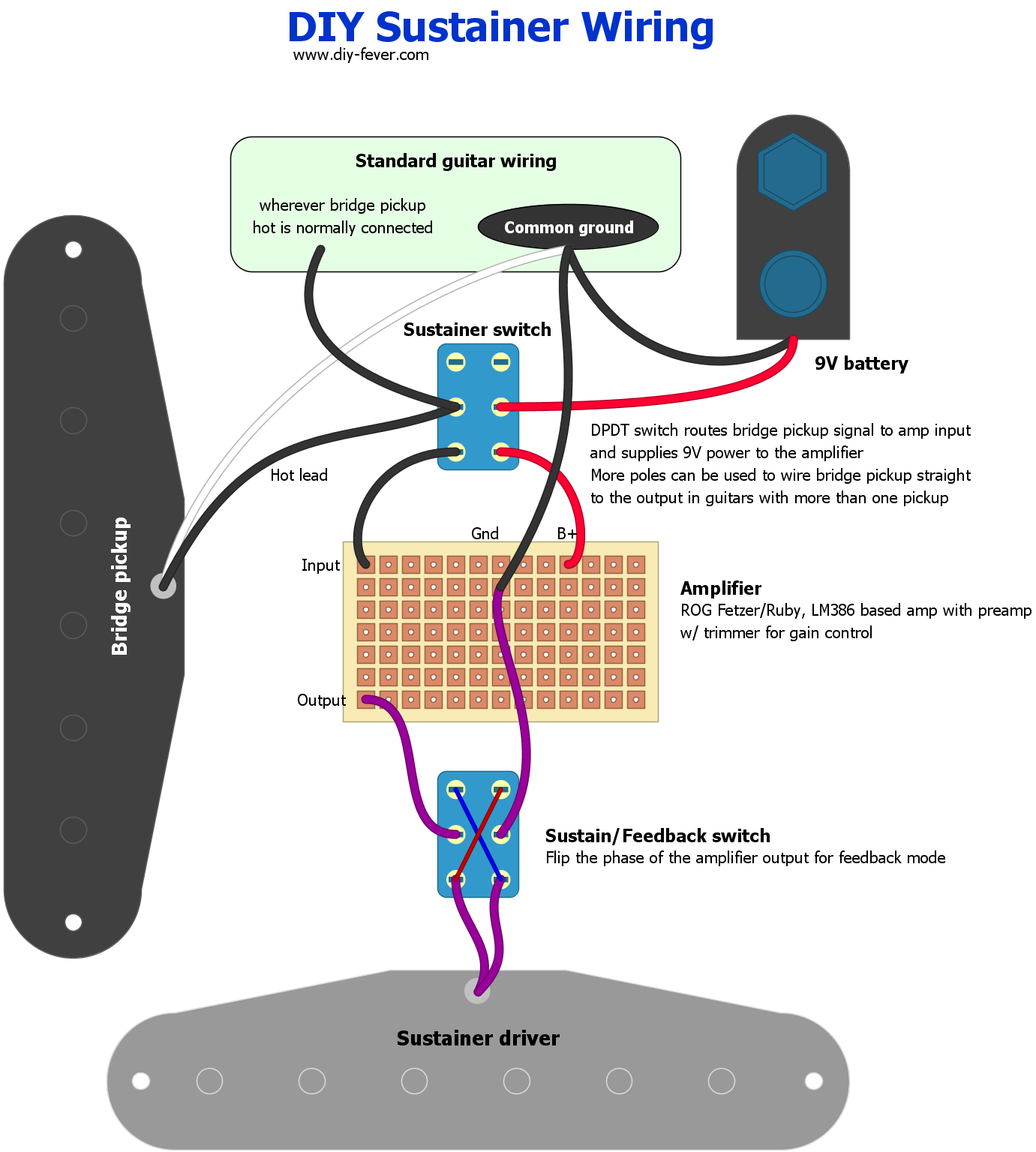
By popular request, I updated the article with a proposed wiring for the sustainer driver and circuit. I don’t have ability to test now it as it’s been almost 10 years since I built the sustainer, so if anyone does try it, please leave your comments below. There’s more than one way to do it and it will depend on your guitar. It’s ideal to have only bridge pickup and sustainer in the guitar because it will reduce a chance of interference between the driver and other pickups. Driver emits a lot of EM waves that excite the strings, but other pickups can pick them up too, and that’s not good!
Sustainer can operate in two modes: in phase which amplifies vibrations of the strings making them sustain indefinitely (or as long as the battery has enough juice to power the circuit) and out of phase (harmonic) which makes the guitar feedback with harmonics (listen to some of Steve Vai live performances, like “Building the Church”). The two modes can be toggled using a DPDT switch that flips the positive and negative side of the amplifier output.
As for the main sustainer switch, there’s more than one way it can be wired and in some cases you may need 3 or 4 pole switch. This is the simplest implementation that kills the battery supply to preserve power and when engaged it wires bridge pickup to the amplifier.
Step 6: tweaking
After the driver is installed in the guitar, we need to tweak the Gain and Volume trimmers to make sure that we get enough sustain but not get into feedback and oscillation. I suggest starting with both trimmers around noon and tweaking it from there. We are aiming for infinite sustain that doesn’t increase the level or add distortion. In sustain mode, if you hit the note and it starts amplifying on its own until it goes into oscillation, it means that Volume and/or Gain are too high. On the other hand, if there’s no infinite sustain, we should increase Gain and/or Volume.
Like with the pickups, the driver height will affect how it performs. The closer it is to the string, the stronger it will affect them. Using the same height as a typical guitar pickup is a good starting point and you can tweak it if there’s need.
Useful links
Project Guitar "Sustainer Ideas" thread (very large)
Project Guitar tutorial on building driver
Program for calculating number of turns for given core dimensions and wire gauge
Official Fernandes Sustainer page


![Deep Purple - Lazy [Guitar Cover]](https://i.ytimg.com/vi/7ZyjTZgM2DY/default.jpg "Deep Purple - Lazy [Guitar Cover]")
![John Petrucci - State of Grace [Guitar Cover]](https://i.ytimg.com/vi/K3bYjMICR5g/default.jpg "John Petrucci - State of Grace [Guitar Cover]")

Hi! I just tripped on this website. The owner did reverse engineering on an old Fernandes Stealth AND on the driver, I think you guys should take a look on it:
https://scientificguitarist.wixsite.com/home/sustainer-reverse-engineering
I already built my own, but there is one problem I encountered. Everytime I power my sustainer, the output decreases. It seems the circuit of the sustainer becomes a load to the input.
I wonder if we’re thinking about this backward?
Is it possible to build an audio output, say 5W, that can drive a 8K to 10k load (like a single coil pickup)?
Rather than build the coil, which seems to be the hardest part, just build the audio circuit.
Is this crazy?
Worth trying…I would worry that the thin wire in a regular pickup wouldn’t survive it though 🙂
Any circuits out there that do this? I can’t seem to find any….
Hello, I had a few questions in mind, I attempted this a year ago and made some mistakes and I’m going to do it again. Now I notice that the connection for the driver and to the output is in parallel, I noticed when I had it connected and turned it on the output was cut in half, wouldn’t it be more feasible to have the driver in series with the output? also Is there a specific magnet type and strength I should consider? to add a little reference I would be using a generic LM386 amplifier I bought online (rather than DIY)
https://www.ebay.com/itm/191674422237?chn=ps&mkevt=1&mkcid=28
This is an example of such.
I’m eager to hear your input.
Hm, not sure what you mean by “output in parallel”. In parallel with what? It’s wired identically as the speaker on the schematic from lm386 datasheet with a polarity switch added to flip the phase
https://www.hobby-hour.com/electronics/lm386-20.gif
In the wiring diagram for the sustainer implication the hot is in parallel with the sustainer circuit and the guitar knobs (giving it a second thought I’m beginning to suspect something was incorrect on my part), by output in parallel I meant the pickups output SEEMS to split to the volume and sustainer control, I assumed this to be an error since my overall output was cut in half when I turned on the sustainer.
As far as I know, there’s no other way to wire it. By wiring things in parallel we do not lose the voltage (signal strength), but the current is halved. If you were to somehow wire in series (which I don’t see how), the voltage/level would be halved.
I’ve been wanting to fit a sustainer into my 10 string pedal steel, will the principle of this system work just as well?
If the premise of the driver is to have a low DC resistance, could I get a pickup maker to make a driver for me and I just make the PCB?
Many thanks for your time,
Chris
Hi Chris. I wouldn’t say that the premise of the driver is to have a low DC resistance. Inductance is also very important. If you used regular pickup wire there would be very few turns to get to 8ohms and there would not be enough inductance to drive the strings to vibrate. That’s why you need thicker wire which has lower resistance and needs more turns resulting in higher inductance.
hi Bancika, what is the purpose of two grounds?
Hi, I am curious, too.
not sure what you mean.
It probably won’t work for you now, but for other people who read this article later and have the same question.
There is only one ground but it has two outputs that have to be put on the same cable to the ground of the guitar
this due to the distribution of the components avoiding interference.
hi,i wondering is the drive must be installed on neck position?will it work well if i put it on mid position?
regards
Must be neck position. Otherwise it takes much more energy to get the strings moving, the closer you get to the bridge.
Hello, I was wondering if I could hire you to make me a sustainer pickup and circuit board for my two string slide bass.
Hi. Sorry I don’t have time for DIY project these days. Haven’t built anything in few years. Also not sure if it would work on a bass, the strings are thicker and need more energy to get moving. Cheers
This guy built one and placed it in the middle position on his strat. I’m not sure what is causing the cocked-wah tone. Could that be related to the driver position? Or is it because of the amp he was using in the circuit?
https://youtu.be/QS7wQ_ajo7o
Hi. Thank you very much for this article. Im going to build sustainer and I have two questions.
Do you think i can use humbucker, where one bobbin would be sustainer driver but the second will be a single coil pickup? I think they shouldnt interfere which each other.
The second: what do you think about puting sustainer driver in the middle pickup point (strat) or even at the bridge? Will it have enough strength to swing the strings?
Regards 🙂
You need the sustainer as far from the bridge as possible, so no other position would work I think.
As for the two-in-one, I haven’t tried but people who did complained about the noise. Feel free to try it, it would be a breakthrough if you succeed.
Hi, thank you very much for your article, it is very clear and interesting !
I wonder if it is possible to wrap the wire around the existing wire of the neck pickup in order to still be able to use it, providing that there is enough place, with p-90 for instance.
I understand that the sustainer must be used only with the bridge pickup, I just don’t want to get rid of the existing neck pickup.
Regards,
Brice
I don’t think it would work as the sustainer coil would be further away from the magnetized core and the noise will probably be a big issue as EM field generated by sustainer will be picked up by the regulqr coil and who knows what might come out of that. But no reason for you to not experiment, maybe you come up with something good.
If you are familiar with the Fernandes Sustainer circuit, I have a guitar that came with it and an EMG 81 in the bridge. I hate the tone of the Sustainer as a neck pickup. Is it possible to add a single coil sized pickup next to it and just have the Sustainer function as a sustainer and use the new neck pickup in the traditional 3-way switch manner? Thanks in advance!
Awesome work mate! It looks like there is still things on Internet that worth it.
Is there any video where we can listen this working?
Not mine, but I’m sure somebody else did it.
Steve Hackett from Genesis uses the Fernandes Sustainer in this video : https://www.youtube.com/watch?v=Er2GHuzlUAY. Enjoy!
Hi-
Thanks for such a comprehensive guide! I have a question regarding making the pickup;
I have a humbucker pickup upon which i just unwound one of the bobbins, then wound the cable to 8 ohms and left the other bobbin as-is? Is this ok? Or should I wind both of the bobbins (maybe to 4 ohms each?) and wire them back up in series? If this is the case, I would probably use thicker wire as I only need to get too 4 ohms per bobbin- with the thicker wire giving me better impedance ? Or am I speaking non-sense?!
Cheers, Shaw.
Yeah, you need one bobbin. but you can experiment with two, why not 🙂 Either 2×8 or 2x4ohm. I would use the same 0.2mm wire regardless of the configuration and I would wind only the top part of the bobbin that is close to the strings, as shown on my photos.
Cheers
Hello Sustainer Experts!
I’m looking for the wiring diagram for the early 1990s version of the Fernandes Sustainer.
I bought a used guitar, with a kit sustainer circuit. PCB says “ver 1.1”. There’s a humbucker at the bridge and the sustainer pickup has the old shape that requires a non-rounded cutout in the pickguard. The circuit already has harmonic and mix modes, but no transformer on the pcb.I think the (diy) wiring was wrong, because I couldn’t get all pickup combinations.
This one looks similar:
https://s890.photobucket.com/user/mortadlanuit/FERNANDES%2520Sustainer%2520APG%252060%2520-%25201995%2520-/story
Can anybody help me, please?
Regards, Immo
(roseblood11 on the forums)
Hi Bancika,
I am guessing the two switches are 2 way DPDT switches advertised here: https://www.pedalpartsaustralia.com/index.php?main_page=product_info&cPath=1_14&products_id=1206&zenid=3410c09c405d60750c3b72322f81d7f5
yes