The Ultimate Overdrive

Introduction
I have built and owned a couple of “classic” tube-screamer derivative overdrives and although they are useful for certain applications, I found them to be too compressed and mid-range sounding. They do make good solo boost and tighten low end well, but, I could never make a diode-based overdrive pedal have that open uncompressed raw crunch on low gain settings (think Ritchie Blackmore).
So I decided to give the diode-base overdrives one more chance by building a big daddy overdrive that will let me experiment with as many different clipping options and op-amps as possible to try to find some useful crunch tones and still be able to use it as solo boost. As a starting point I selected Paul C Timmy overdrive which people love for its transparent sound. What also made it appealing to me are the separate bass/treble controls instead of stupid tone control which is a standard on traditional overdrive pedals.
Clipping
Clipping section is the beating heart of every diode-based overdrive. Number and type of diodes determine how much of the signal will be passed through and what will be clipped. Also, different diodes clip in a different manner, so character of distortion will be different. There’s no absolute best clipping arrangement, thus that many different overdrives which share most of the circuit but feature different diodes. So why not make it in a way that would allow as many clipping configurations as humanely possible?
Switchable clipping diodes have been around for a while, most makers put toggle or hidden DIP switches that offer two or three combinations of clipping diodes, but I wanted to take it a step further. My goal is to allow selecting any subset of 7 diodes wired in series…per phase. That would make it possible to do endless combinations of symmetrical and asymmetrical clipping settings. By using seven switches of a 8-pole DIP switch for each side of the waveform we can shunt each diode in the array. The last of the 8 switches of the DIP can be used to disconnect the whole diode array from the signal chain. Without any clipping diodes, we effectively turn the overdrive pedal into a clean booster.
Note that series diode connection is chosen so that we can combine multiple diodes and achieve higher headroom. Less we clip the signal, less compressed and overdriven it is.

diodes

The same concept can be used to create a drop-in module and mod any existing diode-based overdrive, as long as there’s room for two DIPs and all the diodes.

Diode Selection
  • Germanium: clips softly at 300-400mV. I used 1N34A, but bretty much any old germanium diode will work here and produce similar results.
  • Silicon: 1N4148: clips a bit harder at 600-700mV, standard for vast majority of overdrive pedals. I put two of them in the diode array to be able to match stock Timmy setting with two diodes per side in addition to using a single diode. I used 1N4148, but most other silicon diodes can be used with the same performance.
  • Rectifier: these are also essentially silicon diodes, so they perform similarly to 1N4148. I had some UF4007 that I like using for rectifiers, so I used these.
  • Schottkey: some of them have even lower forward voltage drop than germanium diodes. I used BAT46 that clip at 250mV and also got some BAT41 as well so I can mix, those clip at 400mV.
  • MOSFET: there are few different ways to wire a three legged transistor and use it as a diode. The one that’s different than a regular silicon diode uses drain and gate connected together, acting as a cathode and source acting as an anode (for P-channel MOSFETS it will be reversed). MOSFETs clips a bit softer than silicone diodes at higher voltages, usually between 1.5 and 3V. They need another diode in series to polarize them because it has a silicone intrinsic body diode pointing the other way. Unless we use another diode to polarize the FET, the silicon diode will clip the other phase of the signal. I intentionally left it up to the user to choose which of the remaining 6 diodes, if any, will be used together with the MOSFET. MOSFETs (often BS170 or 2N7000) are used by some “boutique” overdrive/dist pedals, like Fulltone OCD. Because MOSFET can clip the signal both ways, we can achieve asymmetrical clipping using only one MOSFET that clips both phases. I used BS250: P-channel MOSFET.
  • LED: different colors have different forward voltages, but clipping characteristics are about the same. They have high headroom due to high forward voltage drop and they clip harder than other diode types. Infra-red can get as low as 1.5V, and ultra-violet as high as 4V. Other colors will fall in between. I suggest getting LEDs with as low voltage as possible, so that we can get some of that clipping at all.
Asymmetrical Clipping

Asymmetrical clipping is sometimes used as a way to add some “flavor” to the tone. What it means is that we use different types or different number of diodes for each phase, so signal gets clipped differently on positive and negative side of the waveform. However, I found that arrangements where ratio between the total forward voltages between the two sections is higher than 2 tend to sound ugly. That means that it’s perfectly fine to use 1.5V on one side and 2V on the other, but I would avoid combinations that have say a germanium diode (375mV) on one side and blue LED (3V) on the other. But I encourage you to try it and decide for yourself 🙂

IC selection
Another important part of overdrive character is the op-amp. It amplifies the signal before it gets clipped and then amplifies the signal again for the output. Pretty much any dual op-amp with the standard 8-pin DIL pinout will work here. I installed a wire wrap IC socket to simplify swapping op-amps and ordered a handful of most commonly used op-amps to try:

  • NJM4558D: high gain bipolar op-amp, used in Tubescreamer and countless similar overdrive pedals.
  • JRC4559D: stock chip in Paul Cochrane’s Timmy and Tim pedals. Similar to 4558D, but with a tad more gain and faster slew rate.
  • LM1458N: low power consumption op-amp. Reported to work really well in Timmy, bringing more clarity.
  • TL072ACP: commonly used, low noise and low power consumption JFET op-amp.
  • LF353N: wide bandwidth JFET input op-amp.
  • OPA2134PA: hi-fi audio FET op-amp.
  • NE5532P: bipolar input op-amp, higher current consumption than the rest of the heard.

So far I only really tried two of them. NJM4558D was my first choice and it works really nice, lots of drive and resembles Tubescreamer with that almost nasally sound midrange hump. Then I tried OPA2134PA which is wider band and more neutral sounding and really liked it, so it stayed there.

Parts and Construction
As always I aimed for highest quality parts available and I wanted a “hand-wired” point-to-point construction. The circuit is relatively simple so I thought I could pull off an eyelet board. Other than looking super cool, like a vintage amp, eyelet boards are very sturdy (1/8″ thick) and can take a lot of abuse with soldering, desoldering and playing with components. To make for a more compact layout I got some #35 Keystone eyelets which are smaller than #45 that are traditionally used for tube amps. It also means that you can pull less leads through one eyelet and you should be careful with wire as it can only take thinner wire together with component leads. Other parts include:

  • Dale resistors (cool CMF brownies)
  • Nichicon poly film caps
  • Cornell-Dubilier 1uF poly film caps
  • Panasonic FM electrolytic caps
  • Mill-max wrap IC socket
  • Neutrik jacks
  • Alpha 3PDT switch
  • Alpha 16mm pots
  • 1/8″ thick home-made eyelet board with #35 keystone eyelets. Note that they are smaller than #45 typically used for tube amps.
  • CM 8-pole DIP switches
  • Teflon #20 AWG shielded wire for longer runs
  • Thin #28 AWG ribbon wire for wiring controls

DIP switches are rarely exposed for users to mess with all the time, but I wanted to avoid having to open the pedal each time I wanted to play with the clipping section. This made construction a bit more complicated as it required having two rectangular holes in the enclosure and mounting DIP switches on the back of the circuit board. Having no specialized tools for rectangular holes, we drilled a bunch of small round holes and then filed the hole into shape using small flat files.

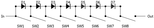
As you can see on the layout, 16 DIP pins are connected to only 9 eyelets. Clipping diodes zig-zag from one eyelet to the other and all but the outer two eyelets connect two neighboring pins of the switch. I wanted to cover as much ground as possible, so I hardwired 4 diodes and installed socket pins for the remaining three so I can experiment even more if needed. Every other diode uses sockets, so I only need to have up to one socket pin per eyelet.

Finally, a top tip for playing with DIP switches: use the tip of the pick to flick the mini switches.

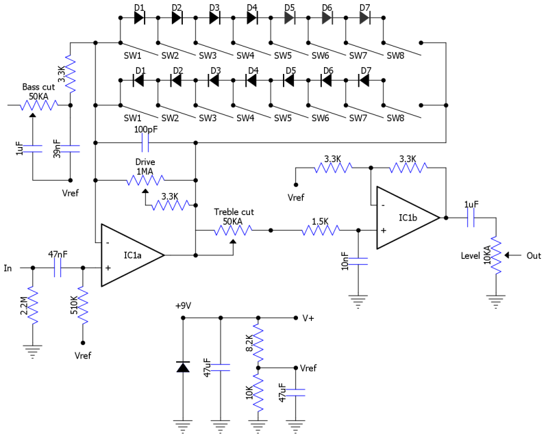
Schematic and Layout
Overdrive Schematic
PDF Layout File
DIY Layout File (right click and choose ‘Save As’)
Results
Pictorial

Click on an image to see more details.
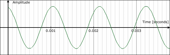
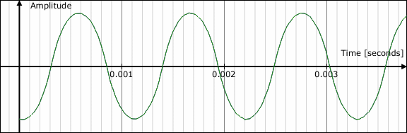
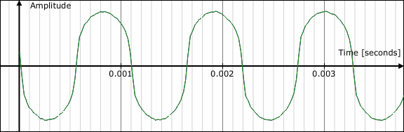
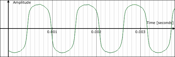
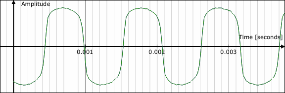
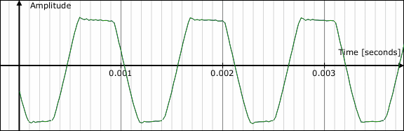
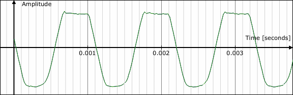
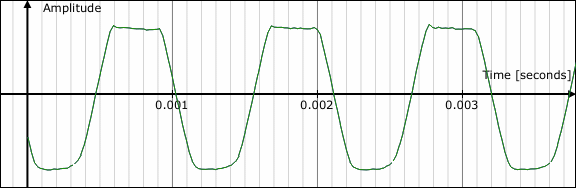
Video Clips

Click on a thumbnail to play the video on YouTube.

Click here to list all 0 related video clips.

Scoping the Output
Curious to see how different diodes clip, I made a simple (and almost free) setup that allows me to pass a 1KHz sine wave through the pedal with gain knob maxed, bass and treble cut at zero, and analyze the output (check out this article for more details). Of course, it’s far from professional scopes, but is enough to give some insight into the world of clipping. Since diodes have different forward voltage, each of the option produces output of different loudness. For example, LED produces output that is 10 times as loud as Ge diodes. I tried to normalize output of each clipping diode using pedal’s level pot trying to get them all to the same volume, so it’d be easier to compare the wave forms. Below is the result.

Clean sound with no active diodes, pretty much perfect sine wave.

Clean sound

Germanium diodes (1N34A). Much lower output and very soft clipping. The resulting waveform still resembles the starting sine wave, it’s just a bit compressed (both visually and sonically).

Germanium diodes

Schottkey diodes (BAT46). Low output, similarly to Germanium, but slightly more compressed.

Schottkey diodes

Silicon diodes (1N4148). Even more clipping and much higher output.

Silicon diodes

Rectifier Diode (UF4007). Very similar to silicon diodes, which is to be expected, as rectifier diodes are also silicon composition.

Rectifier Diode

Output op-amp stage clipping without any clipping diodes active. This proved to be the biggest obstacle when analyzing diodes with higher headroom (LED and FET), as they let more signal pass through which in turn overdrives the output gain stage. We are trying to analyze the output signal of the pedal, but op-amp clipping will “pollute” diode clipping that you are trying to capture. If we turn down gain to avoid output stage clipping, we’ll also drop below the clipping threshold of the diodes, so output signal will be pretty clean. That’s why I also had to analyze the output of the first gain stage, before it gets clipped by the output op-amp. As you can see, op-amps clip hard and sudden.

Op-amp clipping without any diodes active

FET (BS250) and Schottkey (BAT46) diode in series. Noticeably more compression and distortion. As you can see, this wave form resembles op-amp clipping and that’s exactly what happens here.

FET + Schottkey

LED (5mm RED). Again, output op-amp clips the signal and turns it almost into a square wave.

5mm RED LED

Comments
47 Responses to “The Ultimate Overdrive”
  1. jullian says:

    newbie here. can i ask the connections for the spdt switch. please

Leave A Comment

  • About

    The idea behind this site is to share my experience with Do It Yourself approach to guitars, amplifiers and pedals. Whether you want to save a couple of bucks by performing a mod or upgrade yourself instead of paying a tech, or want to build your own piece of gear from scratch, I'm sure you will find something interesting here. Also, this is the home of DIY Layout Creator, a free piece of software for drawing circuit layouts and schematics, written with DIY enthusiasts in mind.