3W Tube Power Amp
In loving memory of my grandmother. She passed away a day before I finished this amp. We’ll always remember you, Nana 🙁
Background
I wanted to have a small but nice sounding tube power amp that I can use with my preamps and pedals. Having a separate power amp is very flexible, since you can combine it with any preamp you want. Also, I wanted it to be able to be a standalone clean amp without a need for additional pedals to drive it.
Circuit
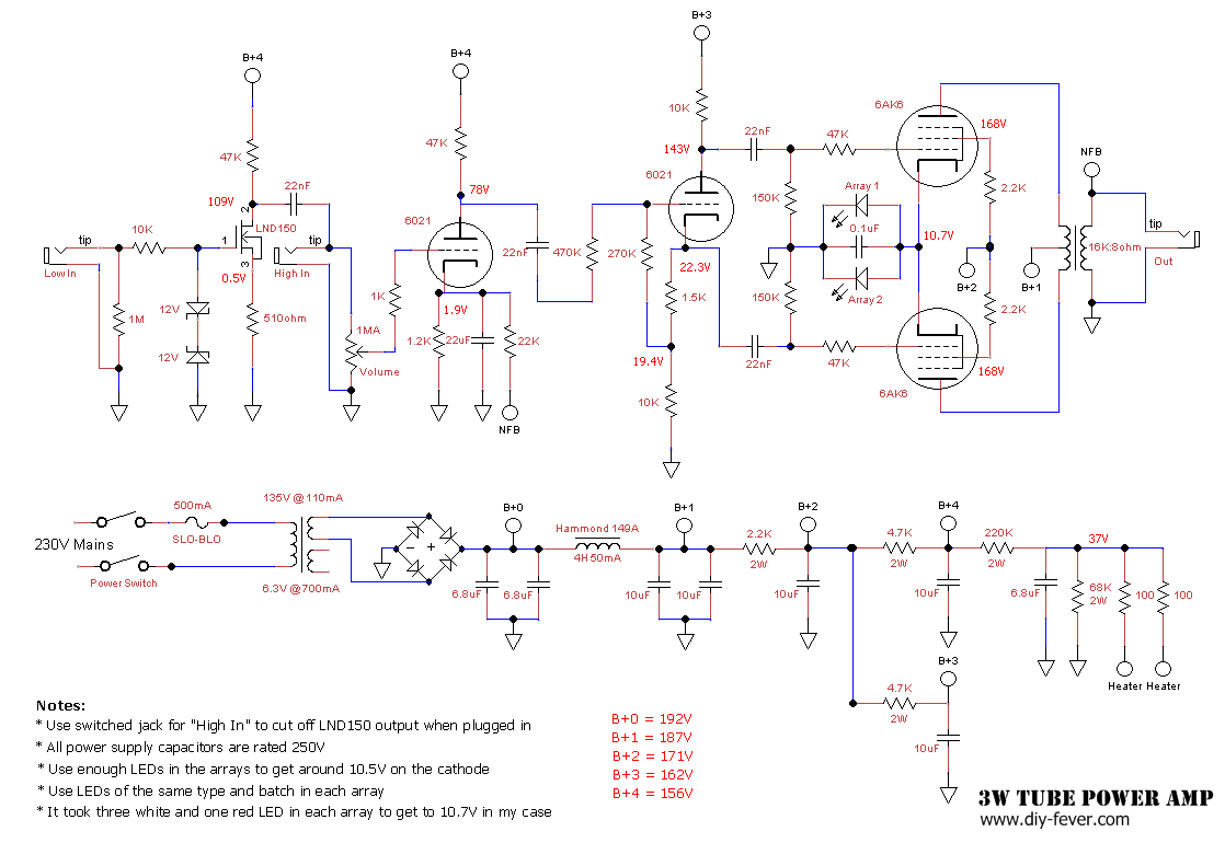
- LED cathode bias for output tubes. As long as the LEDs are lit, they provide a constant voltage at the cathode, so it should sound more like fixed bias, without the added complexity of the bias circuit. For more powerful amps that use higher bias voltage and draw more current this wouldn’t be practical, but here it was sufficient to use two arrays of few LEDs to get the desired cathode voltage and current handing. I used a standard loadline calc to determine the bias point of -10.5V for the grid (or +10.5V at the cathode). Quiescent plate current is about 11mA per tube, plus few mA for screen. That’s enough to keep the LEDs glowing, but I used two arrays of LEDs to make sure they can take the higher current at higher signal levels. Two arrays should be able to handle 50mA without problems. As far as getting to 10.5V, I hoped to achieve that with three white LEDs, but the ones I got had slightly lower Vf, so I added one red diode in each array for total Vf of 10.6V. The two LED arrays should be matched, so the current is distributed evenly across them.
- A choke is applied at the beginning of the power supply, so it filters even the current for the power tubes.
- Two inputs, one goes directly to the 6021 gain stage, and one that uses a LND150 gain stage to boost low level guitar signal. That way I can plug a hot pedal or preamp straight to the 6021 gain stage, and plug guitar in the boosted input to be able to drive the output to its full potential. In front of the LND150 there are two 12V zeners that are supposed to protect the LND150 which has max gate-to-source voltage +-20V.
- Apart from one Sanyo solid electrolytic serving as cathode bypass capacitor from the preamp, no electrolytic capacitors are used, even in the power supply. Poly caps have lower ESR and will not drift over time like electrolytics. Also, they are not *that* expensive. I got five of Vishay 10uF 250V caps for about $10 and added few of 6.8uF 250V I already had. The biggest problem with film caps in the power supply is their size. For bigger amps that require 450V or higher voltage rating and more capacitance, capacitors get much bigger, but it’s not a problem here.
- Cathodyne phase inverter using one spare 6021 triode.
Schematic and Layout
Parts
- Custom aluminum chassis, 26x17x9cm big (or small), powder coated in cream.
- Custom wound toroid power transformer with 135V 110mA and 6.3V 0.7A secondaries. You could use two standard transformers back-to-back to achieve the same thing. For example 230:6.3V (~2A) and 230:9V (1A) wired backwards, or 120V:6.3V (~2A) and 120V:5V (1A) for US mains.
- Custom wound ridiculously overspec’d output transformer with 16K primary and 8ohm secondary. Hammond 125B or 125C should work fine too.
- Hammond 194A choke rated 4H at 50mA.
- NOS RCA 6AK6 power tubes.
- NOS Raytheon 6021 submini tube.
- A few 10uF 250V poly film Vishay capacitors and some 6.8uF 250V poly film (don’t remember the brand) in the power supply.
- ERO poly film coupling caps.
- Mostly Xicon resistors.
- NKK toggle switch with LED on the tip of the lever. Great quality and saves space for a power indicator light. I power the LED off of heaters, using one rectifier diode in series with the switch and one 510ohm resitor to drop the voltage.
- Cliff UK isolated jacks.
- CTS volume pot.
Datasheets
Supertex LND150
Raytheon 6021WA
RCA 6AK6
NKK M2100 Illuminated Toggle Switch
Construction
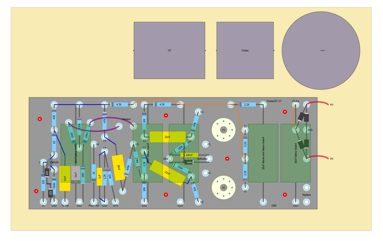
The circuit is layed out on an 1/8″ thick eyelet board for durability and flexibility. Since it’s a new circuit, not verified over and over again, it’s important to be able to easily replace or add components if needed. All tubes are mounted directly to the board, but using traditional chassis mounted sockets. That way I get compact layout without drawbacks of PCB mount sockets. LND150 and 6021 are installed using gold plated pins from IC socket pin strip. That way I can change them if needed without desoldering. Most of the filter caps and twisted heater leads are installed below the board. By using all three dimensions, we’re saving some space and ensuring that heater leads are as far as possible from signal leads. Also, I tried to have heater runs go behind the filter caps which act as a shield, since one side is grounded. I used hot glue to mount the filter caps to the board and make sure they stay put.
Pictorial
Click on an image to see more details.


")
![Deep Purple - Lazy [Guitar Cover]](https://i.ytimg.com/vi/7ZyjTZgM2DY/default.jpg "Deep Purple - Lazy [Guitar Cover]")
")
 Intro & First Solo Cover")
Hi Bancika,
you might wanna look up the 6F4P Plexi project by dvnator on the net.
He uses Russian ECL84 equivalents, triode-pentones in one package, so it’s 2 tubes per poweramp and about 4W of power. The thing sounds decent and has these easily replaceable tubes in it.
Cheers
Konstantin
Hi Bancika,
beautiful sound and design. I just have a few questions regarding mismatches of some caps in the schematic and the layout not mentioned before, as I am trying to come up with a BOM and source the parts.
– The capacitor between C4 and GND (in parallel with the 1.2K resistor) in the schematic has a value of 22uF while it has a value of 1uF in the layout. Which one is correct?
– You mentioned you used 2×6.8uF on B0, 2x10uF for B+1 and one 10uF for the rest three nodes (B+2, B+3 and B+4), however, it seems that there is an extra 6.8uF after the 220k resistor that is connected to B+4. Is this correct?
I have an additional question regarding the power transformers for US mains. Previously, you suggested to use two transformers: 120V:6.3V (~2A) and 120V:18V (1A) for US mains. Is it correct to asume that the output of the 120V:18V (1A) transformer should be connected in series with the 120V from the mains in order to get the ~135V (110mA). I am asking this as I have not been able to source a transformer close to 135V in the secondary.
Thanks in advance for your attention and any information you can provide.
Hey Victor,
– I can’t remember which capacitor I ended up using. 22uF is a standard Fender value that lets pretty much all bass through. I think I used 1uF which tames some of the bass. I suggest trying both and deciding for the one you like better.
– No, the extra 6.8uF capacitor you see is for heater DC elevation circuit. On the layout it’s drawn as 10uF electrolytic capacitor.
– No, you need to wire the transformers back-to-back. But I think I made a type for US market transformers. The second one cannot be 120:18V, but 120:5V. You need to take 120:6.3V and wire 6.3V to DC heaters AND to the secondary wiring of the 120:5V. Then the primary of the second transformer will output around 135V AC. I think you can easily find a single transformer in the states that will work fine.
Cheers,
Bane
Helo Bane,
thanks so much for your answer. I found a 120V power transformer that outputs 140V 100mA in one of tis secondaries. Would this work for the 135V 110mA output required?
Thanks again for your attention.
Best regards,
Victor
Yes, that should be fine.
One last question. Is the 6.3V output of the transformer connected directly to the heater of each of the 6AK6 (between pins 3 and 4 according to the schematic of the 6AK6) while the heaters of each of the 6021 triodes to the 100 Ohms resistors?
Thanks again.
Not really. 6.3V secondary connects to all tube heaters, wired in parallel.
There are two additional resistors coming from 6021 tube (doesn’t really matter which tube it is, since they are all in parallel), but those only serve as a virtual center tap for the DC elevation circuit. You still need to provide 6.3V heater voltage to that tube.
So, if I understood correctly, the heaters of all of the tubes are connected in parallel to the 6.3V and to the two 100 Ohm resistors. Right?
Thanks so much. This is the first time I use a tube in any circuit.
Would a normal PPIMV work with the Diode biasing scheme? Also, could a zener be used instead of an LED array?
Any phase splitter type will work. As for the zeners, I heard that they would be too noisy and are not recommended. Let me know if you do give it a try, I’m also curious.
To clarify, I was wondering how to add a post-PI master volume (PPIMV) to this without affecting bias? I’m not sure since this isn’t really cathode bias or fixed bias, but a sort of hybrid.
Yes, you can use PPIMV. To me this arrangement should be treated as cathode biased because we are lifting the cathode to the desired bias point. But it operates similarly to fixed bias, or regular RC cathode bias with an infinitely large capacitor. Cheers
I love the modular idea! To round it out, you could put a female eurosocket next to the male one, connected after the switch. Like computers used to have in CRT times. That way you could power your preamp from the same point and switch both on and off at the same time.
Also, many thanks for the led-biasing tip. I might use that in my own 6AK6 design.
Thanks for the comment. I have my whole dig plugged into a mains daisy chain that has a master switch, so I turn everything on and off using one switch. Cool idea though.
Cheers!
what are the specs. on the four diodes that are coming off the power transformer?
Any rectifier diodes capable of taking that voltage will do. I usually use UF4007.
That amp sounded great! Have you ever tried making a 30 watt version? I have a friend who knows a thing or two regarding these kind of stuff so I was hoping that you can help us build a 30 watt version.
I wouldn’t recommend doing the same thing for a bigger amp, mostly because it’s not practical, for few reasons: a) you need a lot more filtering, if you use poly caps like I did they are going to be huge, b) if you apply LC filter to the whole amp you’ll need a large and expensive choke, c) you’ll need a load of LEDs to bias cathodes of output tubes, I’m talking over a hundred of them.
I’d just make something more conventional with four EL84 or 6V6
Hey there beautiful amp!
I am wanting a small amp for around the house and a pedal platform. Was wondering what that amp cost you to build? Also, I have built many pedals for myself but I have no amp building exp. if I tried a project like this would you be willing to help me get it running. I am aware of the dangers of amp high voltage and stuff. Just thought I would ask. Thnx!
Hi Bancika,
this is a very useful project and sounds very good!
It’s what I’m looking for and I’d like to build this amp by myself, but I’ve some doubts.. Could you please help me?
There are some differences between schematic and layout (some caps value). Which one should I follow for latest values?
According to the layout, you take power for the 6021 heaters from the last two100 ohm resistors of the power supply schematic. I think one of the two 6021 heater pins should be wired to GND. Isn’t it?
Thank you very much.
Fab
100 ohm resistors do not “power” heaters, they just provide balanced heater reference. Some amps have 250ohm pot there so you can fine tune the noise. They are AC powered with elevated ground reference.
Which caps values aren’t matching?
Ah, sorry, now it’s clear to me.
As for differences between layout and schematic, here is what I’ve found:
– cap between LND150 and Volume Pot: 10nF (layout) 22nF (schematic)
– cap between P4 and G3: 10nF (layout) 22nF (schematic)
– 22nF cap between C3 and G2 seems to be connected to GND, in the layout (mistake?), but not in schematic
– two 6.8uF caps between B+0 and GND in the schematic are replaced by one 10uF cap in the layout
– only one 10uF cap between B+1 and GND in layout instead of two caps shown in the schematic
– pink 10uF cap in the layout is replaced by a 6.8uF cap in the schematic
I don’t know if these differences can really affect the tone. Anyway, for now, I’ve to chose which one (schematic or layout) to follow 🙂
Many thanks!
re: 10nF vs 22nF, I don’t remember which values I ended up with. 22nF is standard, 10nF will be slightly tighter but not much.
re: 22nF to ground, it’s a drawing error. What you see going to ground is actually filter cap lead (10uF below board). 22nF goes to output tube gate.
re: filter caps. I used 2×6.8uF on B0, 2x10uF for B+1 and one 10uF for the rest three nodes. Parallel caps are below the board (marked “above and below board” on layout).
Sorry, it was quite clear indeed…
That’s ok. Thank you very much
Hey Mate,
you wrote “Hammond 149A choke rated 4H at 50mA.”. Shouldnt it be 194A? 😉
Greetings
You are right. Cheers
Have you tried using the LND150 as the split-load phase inveter? I’ve heard that if you bias it to have 1/4 B+ over each side’s resistor, you can get a swing very close to 1/2 your B+!!!
That could be really sweet for a clean amp!
I bet it would, for a clean amp. I wanted to be able to drive the output harder, including the PI, to add more mild but nice and warm crunch
here’s an idea for you: put zener diodes across each of the two 150k resistors, to clip the output before the 6AK6s (like the zeners at the low input).
This could give you some cool crunch at lower volumes, if needed.
Dude, That is one bEAUTIFUL AMP ! – man that sounds just as nice – if not better than a all tube SE amp with exceptional trannies! Your playing is as a real as it gets, what a treat. I’ve been messing with building amps, especially tweakin em and really end up liking split bias (even though the Fender Silverfaces caused it to get a bad rep, and Gerald Weber agrees that it’s bad… OTOH Merlin Blencoe confirmed my opinion = good) . I’ve messed around with the LND150’s a lot & am grateful to Hawes TV.
( I posted the above on youtube… 🙂 )
So anyways I was moddin the snot out of a Freyette S.A.S. pedal ( so it could give nice cleans like your dreamy 3 watt amp and go psycho, as designed (S.A.S = Super Angry Shi* ) and it has a bias knob! ….. that puts from 0V to about 2.5V on the grid, with a 2K2 that drops about 2V stock best as I remember.. It’s a TL071with a reverse EQed 100k pot controlled FB loop into a EF86 with a pretty standard pentode pre circuit with 100K load, to a .1 uf coupling to 100k audio taper volume pot -well it really just had to much volume to control it worth a crap if in front of a standard amp, even with it set about as clean as possible… Got everything they way I like it, but ended up needing 3K3 on the cathode, to have reasonable range on the bias knob, and now it’s a little too squishy when runnin it real high gain if the bias is set ridiculously hot – it actually starts acting like a noise gate! Thats what got me taking another look at LED’s for cathode bias, I had read about them in the HiFI world… I’m thinkin of doing a spilt between a resistor and a LED but I only got 1 to 2 millamps depending on where the bias is set, maybe I won’t be able to find a small enough LED, well see.
Thank You
Craig