Flexi Clip
Background
This is very simple and yet useful project to do. The idea is to replace clipping diodes in any pedal with a simple but flexible circuit that will allow user to experiment with many clipping diodes. The most common ways of getting overdrive effect with clipping diodes is putting them back-to-back in the negative feedback loop of an Op-Amp (like on Tubescreamer and similar circuits) or shunt to ground (like on Rat distortion, MXR Dist +, etc).
Diodes will conduct only when signal is above given threshold. When wired to ground or in the feedback loop of the Op-Amp they will clip the signal louder than the diode threshold is. That’s how we get the distortion. Different diode types have different forward voltage levels, so they clip signal at different levels. Also, different diode types will clip the signal in a different way, changing the character of distortion from mild to crunchy to fuzzy.
Typical Diode Configurations
Vast majority of overdrive and distortion pedals that use clipping diodes use one of the following diode arrangements to clip the signal.

|
This figure shows original waveform of guitar signal. |

|
Adding one diode will clip one side of waveform giving asymmetrical clipping. |

|
Changing diode orientation will clip the other side of waveform. |

|
Adding second diode in back-to-back configuration will clip both sides of waveform giving symmetrical clipping. |

|
And finally, putting two diodes on one side or putting different diodes makes asymmetrical clipping where both sides of the waveform are clipped, but one is clipped more than another. Threshold level of diode array is sum of threshold levels of each diode in the array. |
Diode Overview
This circuits lets you try many symmetrical and asymmetrical clipping types combining few most used clipping diodes: Silicon, Germanium, Rectifier, LED and FET (used as diode: Drain and Gate for cathode and Source for anode). Below is chart of forward voltages I measured on all parts used here.
|
Measured forward voltage
|
|
|
SI 1N4148
|
~790mV
|
|
GE 1N60
|
~265mV
|
|
LED 3mm red
|
~1600mV
|
|
Rectifier 1n4001
|
~740mV
|
|
Schottky 1N5819 (or BAT46)
|
~205mV
|
|
FET BS170*
|
~810mV
|
* FET used as a diode needs another diode in series to polarize it. This measurement includes a Schottky diode in series with the FET. Schottky diodes have the smalles forward voltage drop, so they raise the clipping threshold as little as possible. Other diodes will work too, but would clip a bit less because a sum of forward voltage drops would be higher.

Germanium diodes
Most circuits use either SI 1N914 (same as 1N418), GE 1N34A (or 1N60) or combination of those two so it should be good starting point for experimenting. Germanium diodes will clip the signal softer than Silicon and LEDs have harder fuzzier clipping.
Version 2.0 (2013)
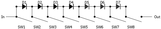
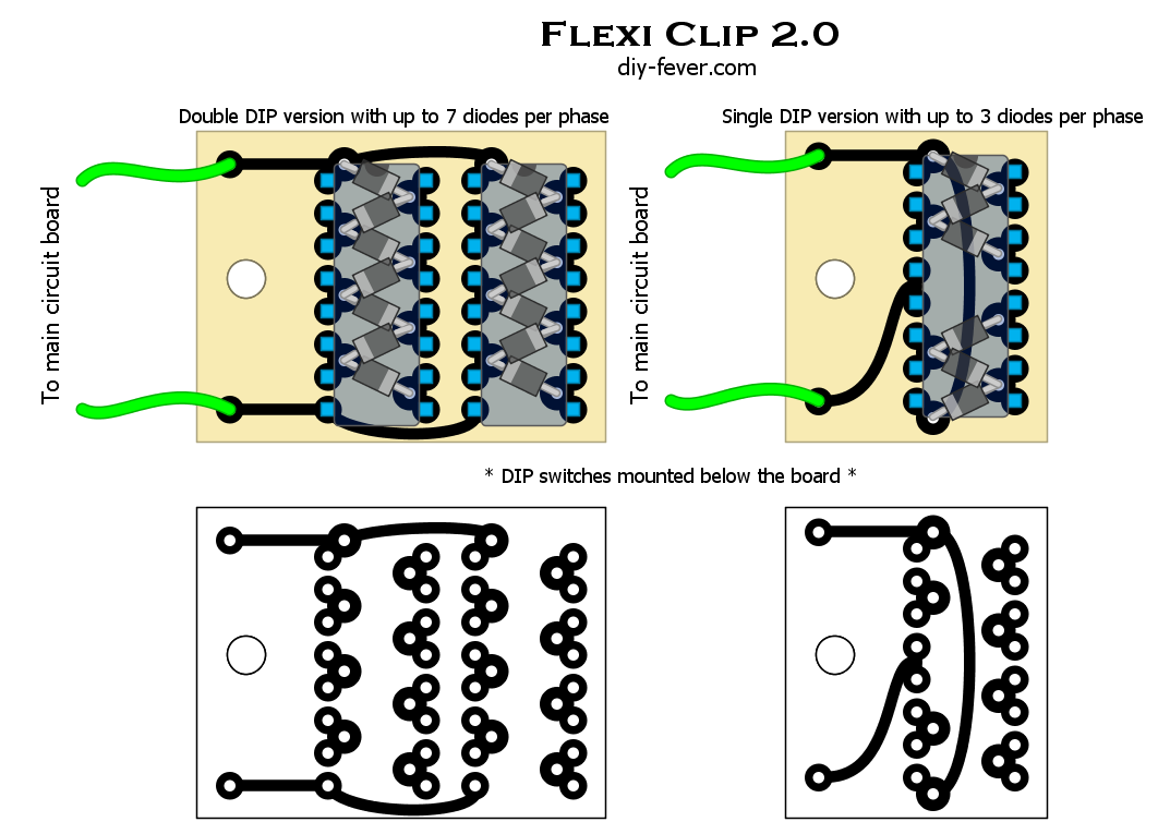
The new and improved version of flexi clip circuit builds on the grounds of v1.0, but adds one important feature: being able to combine multiple clipping diodes. The main idea is to have all available diodes wired in series rather than parallel. Then we can use DIP switch to bypass all the diodes we don’t want to use at the moment. When set to ON position, signal flows through the switch rather than the diode, so the corresponding diode is effectively bypassed. Those diodes which have their corresponding switches set to OFF position are active and will clip the signal (I know, meanings of ON and OFF positions are reversed here). But since we have stacked diode/switch pairs in series, it means that we can combine the diodes and raise the total forward voltage drop, calculated as the sum of forward voltages of individual diodes. Raising the total forward voltage drop will raise the headroom and reduce the amount of distortion and compression. Also, when we combine different diode types, we also combine their clipping characteristics.
To see this circuit in action, check out my Ultimate Overdrive project which incorporates flexi clip as part of the main circuit.
Version 1.0 (circa 2005)
At this point, I wouldn’t recommend building v1.0 of the circuit as you can build v2.0 just as easily and it gives so much more. I’m keeping this section more as a historical reference 🙂 . In this circuit we have 4 diodes per phase, all wired in parallel. DIP switch activates diodes one by one. Diodes in rows a-e clip one side of the waveform and the rest of diodes clip the negative side of the waveform. Switch poles 1-5 control one side of waveform and poles 6-10 control the other. In theory, this arrangement allows having multiple diodes on at the same time, but since they are wired in parallel, effects of each of the diodes will not add up. That’s why only two poles should be ON at the moment: one in each section. As a result, only one diode can be assigned for each side of the waveform, but you still have plenty of options with this setup. For clean boost mode, just set all the switches to OFF position.

Diode types on the layout are those I used for my prototype, but you can use any diode types.

Installation (applies to both v1.0 and v2.0)
Installation to existing OD/Dist circuit is very simple:
- Remove existing clipping diodes.
- If there is second clipping diode per waveform side in original circuit place jumper instead of it.
- Connect solder pads for cathodes (or anode, doesn’t make difference) to input and output of Flexi Clip.

Installation diagram
Useful links
Article on overdrive and distortion circuits
Geofex article on distortion and clipping
DIYStompboxes.com thread about FETs as clipping diodes
")
 Cover")
")
![Lost Without You - John Petrucci [Guitar Cover]](https://i.ytimg.com/vi/CvhLPmLvHVM/default.jpg "Lost Without You - John Petrucci [Guitar Cover]")
Hello !
What FET do you use here please ?
Thanks a lot !
the article calls for BS170, but I have used BS250 with success.
have you ever considered using your device in the feedback loop of any opamp as the “tube screamer” like clone?
is this giving more control of the distortion ?
That’s its intended use. Although you can put it between signal and ground, like Dist III.
Can one use zener diodes here? Like PH4148s..?
I think so
Hello!
Have I understood correctly, that connecting two diodes in series will decrease amount the distortion?
Yes, you’re doubling clipping threshold, so distortion is reduced.
I’ve noticed that your “flexi clip” only clip one side of the signal at a time you switch it on, how about if I want to test a back-to-back configuration or asymmetrical two back-to-back with one?..
dude all you do is slide more than 1 switch across across at a time!! like ‘e’ & ‘f’ for symmetrical, or ‘b’ & ‘g’ for assymetrical. there’s a ton of combinations available from this little unit! the designer of this is a bloody genius! 10 x thumbs up!!!
Why stack the FET with the Shottky?
it gives a voltage of 810 mV + 205 mV = 1015 mV or 1.015V
just a way of obtaining a different voltage that’s all it is mate!
every different voltage you can get will give a slightly different sound!
it’s actually there to polarize the FET and keep it from conducting in the other direction. You can wire FET as a simple diode and then you don’t need an additional diode, but if you wire it like this to obtain softer clipping (G+D – S) you need an additional diode.