Mesa Mark IIc+ Pre PtP
Introduction
Mark IIc+ has a reputation of being one of the most sought after amps today. Only 1500 of them were made back in the 80’s and these days they go for up to 4000-5000$ a piece. One of the players that made this amp famous is John Petrucci. Being a Petrucci fan I couldn’t resist building it, since I can’t afford to actually buy one 🙂 I decided to build a stripped-down version featuring lead channel only without fancy switching. Bass shift and lead bright switches are left in but as board mounted DIP switches. That way I can play with them to find the position I like and leave it like that.
Mods
The last preamp stage on the original IIc+ doesn’t do much as far as overdrive characteristics are concerned. It shapes bass response of the output stage which I don’t have. Voltage divider between 5th and 6th stage reduces signal level to just few volts to make it effect friendly. Since I’m building the preamp only I don’t need the last stage to boost the signal back. Instead, I converted the last stage to AC coupled cathode follower. It’s supposed to be a transparent buffer that will provide nice low impedance output that should drive any effect and long cables if needed. Since it doesn’t cut any bass, it will essentially have similar response like the original stage with deep pulled out. If you want to learn more about AC cathode followers, Merlin has a great article posted here. Large 15uF cathode bypass caps are replaced with 6.8uF poly caps. These were the largest I had and there’s no much noticeable difference in bass response between 6.8uF and 15uF.
Heaters are run at 12.6V to reduce radiation – less current means less radiation and therefore less chance of noise. Also, they are elevated to ~80V using a 220K:47K voltage divider right after the first filter cap.
Schematics

Circuit schematic – click for full size

Power supply schematic – click for full size
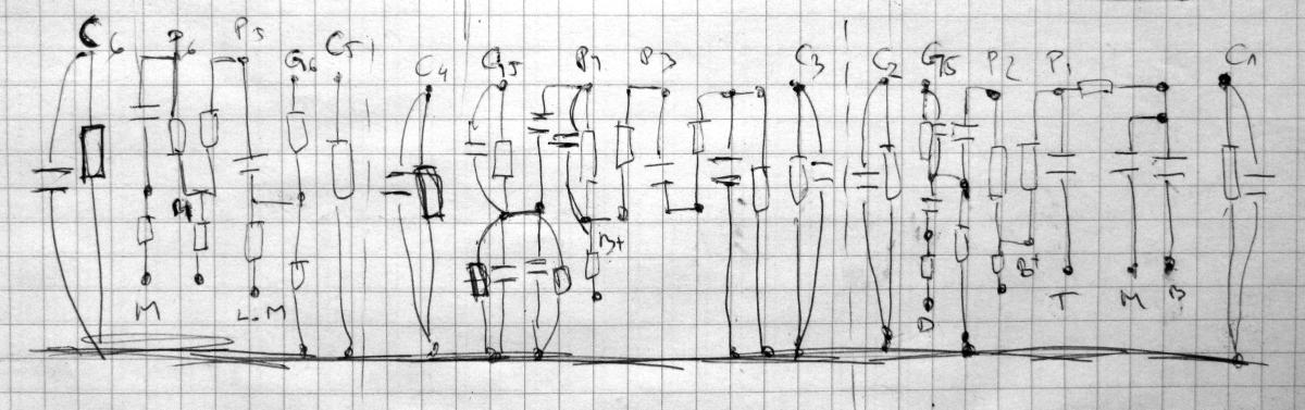
Click here to view hand-drawn layout I used to build the board. Note that it doesn’t include DIP switches and doesn’t show series resistors I ended up using for values I didn’t have. Cathodes, grids and plates are marked Cx, Gx and Px respectively, where x is tube index. T, M, B, etc markings on the bottom side are pot connections; e.g. T stands for Treble.
Parts
There are no electrolytic capacitors anywhere in the preamp! Power supply uses (giant) motor run (not motor start) poly film capacitors. As mentioned before, cathode bypass caps are also poly film. Coupling caps are mostly Russian PIO with a couple of poly film. Small capacitors in the pF range are mix of ceramic and silver mica type. Mica are notorious for being harsh when used as treble bypass/coupling caps so I used them only to shunt higher frequencies to ground. Resistors are mostly Dale and Xicon. 2W metail film resistors were used for plate resistors wherever I had that value. Transformer is a custom wound toroidal built to these specs:
- Primary: 220VAC, 30VA
- Heater secondary: 12.6VAC@0.6A
- HV secondary: 300VAC@40mA
- “Blind” winding: has only one tap and serves as a RF/EM shield
 |
Click to download parts list |
Construction
I used the same chassis like for Soldano Preamp, just a bit shorter and powder coated in cream. It’s a great chassis to work with because each panel may be removed separately. I wired the pots with the front panel removed. Tube sockets are wired before installing it back to allow easier access. Shielded wire is used on the input, from volume pot to the socket and to/from lead drive pot. For circuit board I used two fiberglass perfboards joined together. Doesn’t look as fancy as a nice eyelet board but gets the job done. As you can see below, chassis is packed tightly. Motor run caps are huge and don’t leave too much free space. A couple of times I used two resistors and capacitor to get the right value simply because I didn’t have it 🙂

Chassis layout – click for full size
As far as grounding is concerned, (almost) strict ground bus scheme is used. Thick bare copper wire is used as a bus and is grounded to the chassis very close to the input jack. Components are grounded to the bus in the same way they appear in the signal flow. This also applies to the filter caps. First cap is grounded at the end of the bus and the rest of them are grounded close to the tubes they are powering. All shielded leads are grounded on the input side. Shield on the lead that goes to the Lead Drive pot is used to ground the pot’s lug 3, to avoid using a separate ground lead. Tube socket center pins are grounded to the closest socket mounting screw. This maybe converges from the strict bus grounding scheme, but I reckon it’s fine since it only servers as a shield. Also, internal power transformer shield is grounded directly to the chassis at the same spot where safety ground is connected.
Video Clips
Click on a thumbnail to play the video on YouTube.
 |
 |
 |
 |
Click here to list all 7 related video clips.
Pictorial
Click on an image to see more details.


Result
The first thing I noticed is how quiet this thing is. There’s almost no noise even with both volume and drive knobs maxed. Also, it’s got noticeably less gain/distortion than my Soldano preamp. It’s expected as Soldano has a cold clipper stage and a heavily overdriven cathode follower. Those two also make Soldano sound a bit refined compare to IIc+ which is more raw. Less gain also means more useful tones. With Soldano, I set gain at 20% for rhythm and at 30% for lead. Everything above is too saturated for my taste. With IIc+, good rhythm tones start to happen with both volume and drive set above 50% and for liquid Petrucci-esque lead tones, both knobs need to be cranked up. That leaves more useful crunch tones across knob range.
Having tone stack right after the first stage is cool, but preamp alone without a graphic EQ pedal is useless. You really need to shape the frequency response after the preamp to get some usable tones out of it. Although I have all the parts for the EQ, I left it out intentionally because I plan to build it as a standalone unit. That way I can mix and match Mesa EQ and MXR EQ with Soldano and Mark preamps. Like with the original, bass knob needs to be set very low, 0-10%, to get useful rhythm tones without flabbiness.
After my experience with cloning two of the most sought after and mojo soaked amps of today – Trainwreck Express and Mesa Mark IIc+ I figured that for an amp to be famous it needs to be very bright. So if you’re out there, trying to design an amp that will be next “the sh*t”, make sure it’s bright 🙂

")
![John Petrucci - State of Grace [Guitar Cover]](https://i.ytimg.com/vi/K3bYjMICR5g/default.jpg "John Petrucci - State of Grace [Guitar Cover]")
")
 NO overdrive")
Hi Bancika
I am inexperienced in this. You have B + 1, B + 2, B + 3, B + 4 on power supply schematic. on the сircuit schematic you can see where B + 2, B + 3, B + 4 is connected. Where does B+1 connect to? And what does the “A” symbol mean on сircuit schematic? I plan to use transformer HV secondary: 290VAC@35mA without center tap; Heater secondary: 6.3VAC@1.2A but the heater is connected in a classic way, with resistors to the ground of 100 ohms. Do you think this transformer is suitable? As far as I understand, I won’t have to use 220K:47K voltage divider right after the first filter cap then?
B+1 is connected to nothing, as it’s not filtered enough. Two A symbols should be joined together. I drew it that was just to avoid drawing a long wire.
The transformer you mentioned is suitable. I would still recommend 220:47k resistors to elevate the heater voltage and reduce noise from heaters. In that configuration your 100 ohm center tap would not go to the ground but should go where it says “To V3 Pin 9” instead.
Hi Bancika,
I’m working on a one channel version but with some minor changes. However, I do want to use your idea regarding the elevated heater voltage.
It’s just not quite clear to me yet. What I know is that the heater ‘elevation function’ works as the 220K/47K voltage divider creates a ~70V DC ‘ground’ reference point for the AC heater circuit. (roughly 70V DC, if given a 400V DC input).
In your schematic this point (70V) should be connected to pin 9 V3. You then make the virtual ground 70V. But isn’t that necessary for V2 and V1? And why is it necessary or not necessary?
And in one of your pictures I also see that you have included power resistors between the heater windings and pins 4/5. I don’t see it in the schematic either.
Could you explain this? Thanks in advance.
re: heater elevation, you only do it once, since all heaters are connected to the same power transformer secondary winding. V2 and V1 heaters are still connected to V3, so the elevation applies to all. Ideally you want to do it like this, but you can only do it if you have heater winding with a CT. If not, one of the tube’s CT can do it.
As for the two resistors, I just used them to drop some heater voltage, my transformer was outputting a bit more than 6.3V.
Okay, that clarifies.
So technically it doesn’t matter if I use option 1 or option 2?
Because in that case I’ll go for option 2.
Maybe adjust the resistor values slightly because of the 70V which might be on the high side, or does that not matter much? In option 1 you assume 48V.
[img]https://i.ibb.co/1sjF05Q/CT-heater-2.jpg[/img]
Option 1 uses virtual center tap formed by the two 100ohm resistors. In that case try to use as close values of the two resistors as possible.
Option two uses heater center tap instead of secondary center tap.
As for the heater elevation voltage, I used higher voltage because I wanted to avoid violating the maximum heater to cathode voltage of 200V for 12AX7. It can get close in cathode follower circuit. 40-70V should be fine.
Thank you for your answer. So technically it doesn’t matter at all whether I use the heater center tap application or the virtual center tap formed by the two resistors? Is this sound wise also not audible and does it not affect the life of the tubes?
I had never seen or read the application with the heater center tap before. But if it doesn’t have any negative consequences, I’ll do it that way.
I have a quad 6l6 amp with single input, possible line out, and 4 ohm and 8ohm output. is there a way to put this circuit to feed to power amp?
Yes, just plug it into the input
regarding the PT specs… i’m a bit confused with some of the labels here..
I keep seeing references to: 300-0-300 for the secondaries/HT leads, but references to 300VAC…
300-0-300 would refer to a total 600VAC??
for a 300VAC, wouldn’t the secondaries need to be 150-0-150?
if using with a full bridge rectifier, 300-0-300 (600VAC) would create ~850V DC…
150-0-150 (300VAC) would result in ~420V DC… this appears to be the approx. B+ target?
Yes, that’s 600VAC with a center tap, equivalent to 300-0-300 notation. Depending on how you rectify it, you can get ~850V DC or ~425V DC. In this design, I used two diode full wave rectifier which produces ~425, not the 4 diode full wave bridge rectifier. Check out this document http://www.hammondmfg.com/pdf/5c007.pdf, as it explains different types of rectifier configurations…the one used here is FULL WAVE Capacitor Input Load. Of course, if you have a 300VAC transformer with no center tap, you can still use “FULL WAVE BRIDGE Capacitor Input Load” with 4 diodes and get the same DC voltage.
thanks for the reply.
i have finished the build!
https://www.tdpri.com/threads/mkiic-inspired-preamp-diylc-layout-drafting.1086877/
used a hammond 369BX w/ 4 diode bridge rectifier, and got the same B+1, 425V.
many thanks for providing your schematic and build thread here. and DIYLC, such a great program!
Very cool, how do you like the sound? I found that mark circuits really need a GEQ after to shine.
It’s incredible.
I’ve never played anything like this.
totally different to any marshall-based preamp, SLO, 5150/6505, etc..
(surprisingly, more gain and saturation than a 40W SLO clone thing i did…)
and even without a GEQ. (although I am planning to build one on a vero board soon)
to be fair though, I have been running it into a 4xEL34 power amp (FX return), then into a fryette PS-100, (with the ‘warm’ and ‘edge’ voicing switches activated – essentially adds a scooped post-poweramp EQ).
Doesn’t really need an overdrive, but you can, it’ll take it, and when you do, it’s absolutely bone-crushing.
Not even that noisy (barely any hum or hiss) with upright PT in a small chassis (13.5″x5″)
Hi Bancika,
Can you please tell me B1, 2 ,3 ,4 voltages as i would like to use some other transformer?
Petat
Aim for B1 around 400V, the other voltages will follow.
How can i combine this with a power amp, i am New into this things
It’s pretty much a matter of picking a power amp schematic and slapping these two together…but it’s not really suited for a total novice. It takes some practice and skill
Hi bancika
What is the wattage of this amp?
With a 1×12″ celestion vintage, is it powerfull enough for a music studio?
No wattage, since it is just a preamp. It needs a power amp to drive a speaker.
Have you looked at other revisions to the circuit? Curious on what you think the key differences are from a tonal perspective and wondering if there’s a way to take the IIB to IIC+ territory using the loop to either add gain or shape the tone
I haven’t, honestly 🙂
Hi there again, sorry to keep pestering you…
can you see any problems in using the kit listed in the link below between your second two channel Mesa MK IIC+ preamp and the power amp stage of the amp project N5X shown in the second link below between the final output 22nf capacitor on your mark II C+ and just before the 22nf (C9) on the N5X schematic.
I can power it with the small 0v-6v 0v-6v 50va torroidal transformer I an going to use to DC power the heaters of all the valves by dropping the voltage using a LM317 adjustable regulator set at 9V.
Also can you see a problem using the 190v-0v-190v transformer to power the 3 JJ ECC83 in your Mesa 2 channel MK II C+ circuit and powering a single JJ el84 or JJ 6v6s (Switchable between them) in the M5X power amp. I’m not going to use the 6.3-0v secondary of the transformer for anything.
I like the M5X output stage because you can reduce the output level without reducing the gain/drive of the power amp.
http://diy.thcustom.com/?wpdmdl=3805
http://www.ampmaker.com/infocentre/thread-120.html
cheers.
Hi Again
I notice it also states that the circuit’s input voltage is -30v (minus) is this correct?
If so how do I obtain a -30v supply with it using the ground earth point as it’s 0v?
Yes, you need negative voltage as those are PNP transistors. There are few ways you can get -30V. The simplest is to use a dedicated transformer to power this part of the circuit. A standard 24V transformer, one of those tiny ones will be fine, as we need very little current. Then you can rectify AC to DC and use negative side as your V- and ground the positive side.
Another way is to use MAX1044 or similar charge pump and multiply voltage to +-33V and then just don’t use the positive side.
Hi there,
I’m looking at Mesa Boogie’s Mk-IV graphic equaliser circuit that you kindly provide a link to. To build this ‘old style’ graphic equaliser it uses inductors. On the schematic it is stating values of these inductors from 1H down to 0.033H.
Is this correct or do they mean uH or mH and forgot to include the u or m prefix?
Yes, those values are correct. You can also replace inductors with gyrators. Here’s how you can do it https://circuitmaker.com/Projects/Details/Ben-Jordan-2/BoogiEQ
Hallo,
I intend building an amp, based on this preamp.
The questions I have are:
– do I have to make changes in order to hook it up directly to a poweramp, that shares the same chasis?
– could you post a schematic for the 5-band EQ, you mentioned in the article, and tell where to integrate it?
– do you have a schematic for a 1-5W tube-poweramp (preferrably push-pull), that uses more common tubes, such as for example ecc82?
– could you maybe make an overall-schematic, for what I indend to do?
Thanks for your efford man, I really appreciate it!
Best regards form germany,
Boschili
Hi,
– you can connect the output straight into the power amp.
– here’s the schematic of the EQ http://i.imgur.com/ZWmwI01.jpg…you can integrate it the way it is in the original amplifier. Or you can put it between my version of the preamp and the power amp.
– you can build the power amp section of Firefly amplifier using ECC82. I would start with this schematic and cut just before V2b http://diy-fever.com/wordpress/wp-content/gallery/firefly/firefly_rev3_mod.png
– that’s a lot to ask 🙂
Cheers
Thanks a lot for your answer!
You really helped me out.
Just one more question:
As I took a closer look at the schematics above in your blog, I reccognized a Voltage “A” being introdiced to the grids of the preamp-tubes twice. Appaently this voltage is not to be found in the in the powersupply or anywhere else. is it possible, that “B+1” (which I could not find in the preamp) shown in the powersupply corresopnds to “A” in the Preamp?
Hey. Points marked with “A” are not voltage references. They should be connected together, that’s all. The part of IIc+ sound is the fact that it has clean channel that bleeds through to dirty channel. That’s what this connection does.
Btw, I suggest you to check out my second version of the preamp as it has more features and ready to use PCB layout.
Cheers,
Bane
Anyone want to sell me one of their 2C+ clones ? msg me kenmasters 007 at hot mail
Hi there,
Could you use the output of this to feed a separate, stand along power amp?
Absolutely. That’s one of my uses for it.
quick question. Could you nd run it directly into a std combo amp ( use as guitar pedal) ? Or would you need to attenuate the signal first?
Yes you can, output is set to approx line level, so it works fine with solid state amps and pedals. I use graphic EQ and delay pedals after the preamp and never had issues.
Hey Bancika, I’m considering making a JFET version of this circuit and see how it sounds in stompbox form. I guess the obvious changes in the circuit would be that I wouldn’t need the power supply section, and I would have to appropriately bias the JFETs. Apart from that, would you suggest making any other changes to the circuit?
It should work as is. You can omit the last triode and just make a simple voltage divider after the 5th triode for volume control. The 6th gain stage is really a buffer and fixed voltage divider before it brings down the levels suitable for pedals. Since you’ll drive your pedal with 9V and not 400V, levels are going to be pedal friendly. So I’d just put volume pot after 47nF cap coming from the 5th triode and take that as pedal output.
Thanks so much for your response! I also made some additional modifications to basically hardwire the lead bright, pull bright, treble shift and pull deep (on the original schematic). I’ll wire it up and let you know how it goes.
Bancika
Thanks for the info an help so far. I have been working on it since about the beginning of November. I am using this schematic (very slightly modded) , AX84 clean preamp (with blues switch) also modded and AX84 20 watt SE power amp. The plan is to make the output tubes switchable EL34 and KT88. Still going to be a while before I am done but I am trying to go all out it. Can’wait to hear how it sounds.
Thanks,
John
Do you have voltage readings for B+1, B+2, B+3, B+4?
Thanks
I don’t have them for this version, but I do have them for the PCB version I made afterwards. You can find them in my other article, listed in the schematic. Cheers
Thank you for the response.
I’m still deciding what I’m to make next.
Thanks again.
I just got a 350-0-350 with 2.5v 5.0v and 6.3v taps.
Will the 350 volt be ok? Or too much?
I will probably make this into a full amp not sure yet though.
Thanks,
John
350V is fine, you can always drop excess voltage.
Sorry to keep bugging you.
Is V1A, V2A & V3A pins 1, 2 & 3 and the “b” section 6, 7 & 8?
Definitely making this into a full amp with a separate clean channel.
Just deciding on either 20 watt single end with KT88, 20 or 50 watt push pull with EL34.
Thanks again.
Thank you for the help.
I actually built the PCB version but did it point to point on a turret board. I had to mod it a little probably because of the amp I made for it (single ended parallel 6L6 I came up with). I did not use either master volume. I just used a 10k to ground instead. I also put the “deep” and “bright” switches in the amp section so it can be used with effects loop (still working on that).
This thing is awesome. Still fine tuning it.
John
Cool, great to hear.
Here’s a video I just did today.
I don’t play that great but this thing sounds great.
The amp is a simple design I came up with from looking at a bunch of other single ended.
https://youtu.be/8XT8XqU63aE