Guitar Wiring 101
Table of Contents
- DIY Layout Creator: how can DIYLC help you with wiring diagrams?
- Single coil wiring: what can you do with single coils and how to wire a Strat
- Humbucker wiring – Les Paul: how to wire a Les Paul or similar guitar
- Humbucker wiring – 4 conductor: how to wire 4-conductor pickups
- Coil-tapping: how to take advantage of coil-tap and get more sounds
- Multi-pole switches: how to get the best out of a Super switch
- Volume controls: how do volume controls work
- Tone controls: how do tone controls work and how to make them better
- No-load tone pots: what are no-load pots and how to make your own
- Treble bleed: what are treble bleed circuits and which one is the best (for me)
DIY Layout Creator
I started building DIYLC back in 2006 with a simple goal to support guitar pedal circuits only. Over time it grew significantly in scope and now it is the most powerful guitar wiring drawing and anlyzing tool around. You can easily plan your wiring – draw pickups, switches, controls, but one of the biggest features is the ability to analyze guitar wiring diagrams. It analyzes the circuit in each of all possible switch combination and tells you which pickups will be active, which controls will operate in which way, etc. That way you can prepare for your build and iron out any issues before even touching the guitar.

DIYLC is open source and free to use, so go check it out here.
Single coil wiring
Single coil pickups are the simplest to wire because they typically have only two leads – hot and ground. Some humbuckers have their coils connected internally and are pretty much the same to wire as single coil pickups. That’s why we will call them both “two conductor pickups”. Ground leads are typically connected to a common grounding point and hot leads are switched in and out of the circuit. Let’s take a look at standard Strat-style switch.

Note: looking from the terminal side, bridge terminal is the one closer to neck pickup!
It usually has 8 terminals – two poles with 4 terminals each. Each pole has one common terminal and 3 switched. The first thing you want to figure out is which terminal is common. Note that terminal on the left is connected to the lever all the time – that’s our common terminal. The other three terminals are connected to the lever only in certain switch positions. Represented as a schematic, each pole would look like this.

The only difference between 3 and 5 way switches is that 5 way switch connects two terminals with the common in positions 2 and 4: center and one outer terminal. Schematic above shows position 2 that connects both bridge and middle terminals; image below shows how it’s typically represented on diagrams.

To wire three two-conductor pickups we only need one pole. Common goes to volume pot input and 3 switched terminals are connected to pickup outputs. That way, we will select one pickup in positions 1-3-5 and two pickups wired in parallel in positions 2-4. When middle pickup has reverse polarity, noise will cancel out in positions 2-4 and they will be wired in so called “humbucking” mode.
We will use the remaining pole to switch tone pots. Typical strat wiring has two tone controls – one for middle and one for neck pickup. We want to switch neck/middle tone control on when neck/middle pickup is on. To do this, common terminal of the second pole is connected to the common terminal on the first pole (pickup output) and neck and middle terminals of the second pole are connected to their respective pots. When neck pickup is on, the second pole will switch the output to the neck tone control as intended. What happens in position 4 (both neck and middle pickups on)? Both pots will be switched on and will be in parallel. Moving any tone pot would change the overall resistance to the tone cap and change the tone. The result is below:

Humbucker wiring – Les Paul
Les Paul style pickup selector switches are simple and easy to wire. Complicated part about wiring a Les Paul is having separate tone and volume controls for both pickups and having longer leads between control cavity and the switch.

I’ll go through standard Les Paul wiring and explain what happens in each position.
- Lead position (bridge pickup only): switch connects bridge pickup terminal to the output terminal(s) but leaves the neck pickup unconnected.
- Middle position (both pickups): both pickups are in the circuit and connected to the output terminal which makes a parallel connection (note that both pickups are still internally wired in series, but neck and bridge are combined in parallel).
- Rhythm position (neck pickup only): the same as for the bridge pickup but in reverse – bridge pickup gets disconnected, but the neck pickup gets connected to the output terminal(s).
Note: unlike Strat-style wiring, volume and tone controls come before the switch and switch output goes directly to the jack.
Humbucker wiring – 4 conductor
4-conductor humbuckers are fun to wire because they offer many combinations to play with. Some pickups have another bare wire which is there for shielding and should always be grounded. Manufacturers have their own color code, so make sure you find the right color code before connecting anything. Below is color code diagram for common pickup manufacturers.

To verify that you got the leads right try to measure DC resistance across each pair of leads. Leads that belong to the same coil should measure a couple of kilo ohms, and if they don’t they should measure infinity.
Coil-tapping
This technique is only possible with 4-conductor pickups or pickups that already have coil-tap lead instead of all four leads. Coil tap is a connection between two coils in a humbucker and is sometimes referred to as “series link”. Vintage style pickups have their coil tap enclosed in the pickup which means that we can’t play with it. Having coil tap gives us a couple of wiring options:
- Series coils (standard): connect the hot lead to output, ground lead to ground and leave the coil-tap unconnected. Provides the most output.
- Splitting the humbucker #1: by grounding the coil-tap and connecting the hot lead to output we’re rendering the coil closer to ground useless because both of it’s leads are grounded. What we’re left with is the coil closer to the hot lead. Since we only have one coil, it will not be hum-cancelling on it’s own. It’s common to split a humbucker, so it can be wired with another coil in parallel, making the noiseless combination, especially on H-S-H guitars.
- Splitting the humbucker #2: by grounding the hot lead and connecting the coil-tap the output we’re left with the coil closer to ground. Some pickups have asymmetrical coils and even symmetrical coils will sound different because the one closer to bridge will sound a bit brighter. That’s why it’s useful to have both options available.
- Parallel coils: coil tap connection needs to be broken for this kind of wiring, so three lead pickups cannot be wired this way. The idea is to join start of each coil with finish of the other coil. One on those connections will be hot, the other ground. Parallel coils will sound more like a single coil sound, noticeably quieter and shallower than a series connection.
Multi-pole switches (aka 4-pole switch, aka Super switch)
These are the most versatile 5 position switches around. They have 4 poles, each pole has one common and 5 switched terminal which makes a total of 24 terminals. With that many connections you can wire pretty much any pickup combination you can imagine. Poles are mounted on two wafers, two poles each. Common terminals are usually the outer two terminals on each wafer. Image below shows multipole switch, two poles on the front wafer are outlined with different colors.

Diagram below shows switch diagram with all 4 poles outlined in red and all terminals marked – C stands for “common” and 1 through 5 are terminals that get connected to the common in a certain position.

The only downside is that these switches are physically larger than most other switch types and mounting them in cavities routed for some smaller switch may be tricky.
Now, let’s go through one example of wiring using a Super switch and hopefully you’ll figure out how it works somewhere in the process. Below is a diagram taken from DiMarzio site and wires two humbuckers. I marked poles 1-4 right next to the common terminals.

- Position 1 (bridge humbucker, series connection): poles 1, 3 and 4 do not have any effect in this position because nothing is connected to terminals that correspond to position 1. That leaves us with pole 2 which connects bridge pickup hot lead to the output (volume pot input).
- Position 2 (outside coils, parallel connection): this one is more exciting because all poles do something. Pole 1 connects bridge pickup coil tap to ground, effectively splitting the bridge pickup. Pole 2 connects bridge pickup hot lead to the output. Pole 3 connects neck pickup coil tap to pole 4 which connects it to the output. What we end up with is a coil from bridge pickup coil tap to hot lead and a coil from neck pickup ground to the coil tap. Because of the way poles 2 and 4 are connected, these two coils will be paralleled.
- Position 3 (both humbuckers): Poles 1 and 3 do nothing, so we’ll ignore them. Pole 2 connects bridge pickup hot lead to the output and pole 4 connects neck pickup hot lead to the output. Each humbucker has it’s coils connected in series and humbuckers themselves are connected in parallel.
- Position 4 (inner coils, parallel connection): This is similar to position two just inverted. Pole 1 connects bridge pickup coil tap to the output through pole 2. Pole 3 grounds neck pickup coil tap and pole 4 connects neck pickup hot lead to the output. That leaves us with bridge pickup coil from ground to coil tap and neck pickup coil from coil tap to hot lead. Again, they are paralleled.
- Position 5 (neck humbucker, series connection): This is similar to position 1. Poles 1, 2 and 3 do nothing and pole 4 connects neck pickup hot lead to the output.
Volume controls
Volume pots are wired as simple voltage dividers. Higher settings have higher resistance to ground and lower series resistance, so more signal passes through. When maxed, volume pot has zero series resistance and full pot resistance to ground. Signal takes the path of least resistance and most of it will go though. However, some signal, mostly treble will be lost. With low pot values (250K) it will be more noticeable than with higher (500K and 1M) pots. That’s why typical pot values for brighter single coil pickups is 250K and for warmer humbuckers 500K or sometimes even 1M.
Typical volume pot setup is shown below. Input goes either directly from the selector switch (Strat style, master volume control) or from hot pickup lead (Les Paul style, separate volume controls). Output goes either to the output jack for Strat style guitars or to the switch for Les Paul style guitars.

Another thing to bear in mind is pot taper. Two most commonly used tapers are linear and logarithmic. Linear taper, as name suggests, linearly increases resistance throughout it’s range. That’s ok for some applications, but not for volume pots. Our humanoid ears work in logarithmic fashion, so volume pots need to have logarithmic taper in order for us to hear smooth transition between quieter and louder settings. If volume jumps suddenly in the first 20%-30% of volume pot range and then does almost nothing in the rest of the range, it’s likely that you got a linear pot instead of logarithmic.
Tone controls
Most guitars have at least one tone control installed. They can be either assigned to a particular pickup (Strat or Les Paul) or work as master tone control (Ibanez and others). Electronically, it’s a variable low-pass filter. Lower the resistance, more treble gets cut which means that higher pot values will sound a bit brighter (typically 500K vs 250K). Capacitor values usually traditionally range from 0.022uF (22nF) to 0.047uF (47nF) but many people find these values too large and install much smaller caps instead. Values of 10nF, 6.8nF or even smaller are reported to work quite well (I used 10nF in my latest mod). To help you decide between cap values and composition, check out this site. It hosts a couple of useful videos with cap value and composition analysis.
You’ll notice that once it reaches zero sound gets very muddy very fast. That’s because we have zero resistance between the signal and the cap. To prevent this, some people put a small resistor (10K or so) between the pot and the cap. That way we won’t affect pot operation at higher settings (510K is very close to 500K) but at lower settings it will prevent it from reaching zero as we’re always adding 10K in series.
No-load tone pots
Even with tone control maxed some high frequencies get cut. To let all the frequencies through you can either get a no-load pot or make one. CTS makes them for Fender and what they do is simply break the connection between the wiper and conductive element when pot is maxed. Additionally, they have an indentation so once they reach maximum setting they “click” and it’s not that easy to turn them back. To make your own just cut (or cover with nail polish) the element near the end, so that resistance between the wiper and the opposite lug reads infinite when maxed, at lower settings it should read as usual.
Note: no load pots won’t work for volume control! Don’t try to use them.
If you ask me, they aren’t worth the hassle. Fender pots have annoying click and it’s not easy to mess with your own pots for very subtle result.
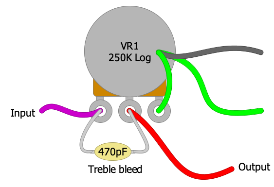
Treble bleed
- Single cap, ranging from 100pF to 500pF, sometimes even bigger. Ibanez uses 330pF on many RG models, some PRS have 180pF or so. This configuration works well with higher volume pot settings, but with very low settings (30% or lower) it gets really bright as most of the signal is attenuated by the potentiometer but all of the high end is “bypassed” by the treble bleed capacitor. I do not personally prefer this setup but it could be useful for some folks to have brighter sound at lower volumes to add some sparkle to cleaner tones.
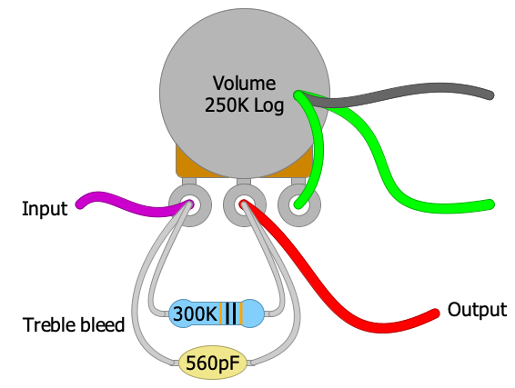
- Cap paralleled with a resistor. DiMarzio and Seymour Duncan recommend this configuration. Typical values are 560pF and 300K. It’s supposed to provide more consistent treble bleed compared to a single capacitor. However, having a resistor paralleled with the pot will affect the pot taper as well. When rolling the pot down it is actually getting closer to a ~190K pot because 500K || 300K gives around 190K.
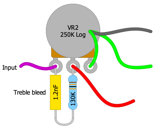
- Cap in series with a resistor (the order does not matter). Kinman recommends this for single coils but it works rather well for humbuckers too! I installed 1nF cap in series with a 130K resistor and it works awesome. Resistor is there to limit the effect of the cap and having it in series with the cap means it shouldn’t affect pot taper as much. Larger cap means wider frequency range, so treble jump isn’t as sudden. So far, this is my favorite treble bleed circuit.
Note: some folks actually prefer volume pot treble roll-off, so you should try few different setups and find the one you like.

are tone pots also log taper, or linear?
Typically, log pots are used for both…but it’s not set in stone. Linear would change the response of the pot and it may be what you are looking for. I prefer log for both.
Wow, useful information here ! And the DIY Layout Creator really rocks, good job.
Just trying to figure out the wiring for my new diy guitar using a Schaller Superswitch M and 2 Humbuckers (4 conductor).
DIY Layout Creator helps a lot, but the analyze Guitar Diagram function drives me crazy and always says the wiring is NON hum canceling, so i lost a lot of my remaining hair 🙂
So I simplified the wiring to a minimum and I think found an error in DIY Layout Creator.
The normal, serial (and hum canceling) wiring of humbuckers always connect South finish and North finish (see also above on the site).
If this is done in diylc it states NON hum canceling.
If North finish and South Start are connected diylc states hum canceling ?
Take care and ty for a reply.
Can you please email me your layout file to bancika AT gmail DOT com so I can try?
Thanks
This was a fast reply 🙂 Did not expect that.
email is on its way ,,,,
Thank you
This guy is amazing 🙂
My problem has been fixed with the current update of DIY Layout Creator !
Thanks mate 🙂
I have a shadow killswitch that I want to hook up to my single conductor EVH Frankenstein pick up but cannot get any help with a schematic.
Thank you so much for this. How about two resitors that are series and parralel with a cap (I’ve seen it in diagrams)? I look forward to trying many combinations in the near future. I also like the idea of using a variable resistor to see what value your ears like best.
Yes, you can do that too, kind of a mix between the two.
When you a have two resistors in series, you just need to add their value. Eg: 400k + 50k = 450k. Hope it helps 😉
Very good information. Thanks for sharing.
regards