DIY Sustainer
Introduction
Sustainer is a cool little device originally designed by Fernandes®. The kit contains a sustainer driver which replaces neck pickup on guitar and a circuit board that contains the electronics. The original Fernandes sustainer also has an active pickup which can be used as a conventional neck pickup when sustainer is not used, but this project does not include that feature. This limits guitar tonal options in one way but gives completely new possibilities.
Here’s how it works. When sustainer is turned on, we take the signal from the bridge pickup, amplify it using a simple audio amplifier and use the amplified signal to drive the driver instead of a regular guitar speaker. Think of the driver as speaker coil that cannot move. The driver generates electromagnetic (EM) field that moves the strings instead of moving the conventional speaker diaphragm. Guitar strings are close to the driver and get excited by the EM field, casing them to vibrate indefinitely. In a nutshell, sustainer works exactly the opposite from a regular guitar pickup. Instead of picking up the vibrations of the strings, it is causing the strings to vibrate.
Keep in mind though, that we cannot use a conventional guitar pickup as a driver because it has very high impedance and DC resistance (typically 5K-20K). Amplifiers usually work with loads between 4 and 8 ohms, so we will need to make our driver very similar to guitar pickup, but wind it with thicker wire and less turns to aim for DC resistance of 8 ohms.
Building your own sustainer is not simple and requires a lot of research and experimenting. Make sure you have basic knowledge in soldering, electronics, guitar wiring and pickup building. Otherwise, this can easily prove to be a painful project and you may be better off buying a real Ferndandes sustainer or Sustainiac.

This photo shows Fernandes Sustainer kit which is cool but very expensive (above 200$). Fortunately, great guys from Project Guitar Forum (most of all Pete/psw and Col) developed DIY friendly project that costs much less than original but still sounds good. Total cost of the build is between 10 and 20 euros (or dollars), depending on what you already have. Also, I’d like to thank PSW Pete for sending me a spool of 0.2mm wire all the way from Australia at no cost.
Step 1: getting a bobbin
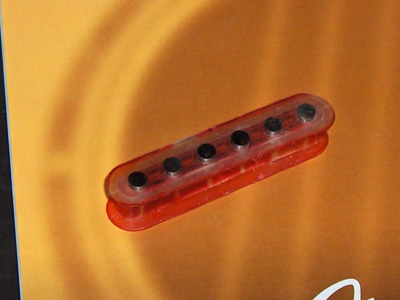
You can buy a new single coil bobbin and pickup cover online or try to salvage one from an old pickup. I got a bunch of them from a friend and picked one that had a bobbin I liked. I used a traditional single coil bobbin with 6 pole pieces which makes for a discrete driver, but many DIY-ers had great results with rail-type pickups, and original sustainer is also rail.
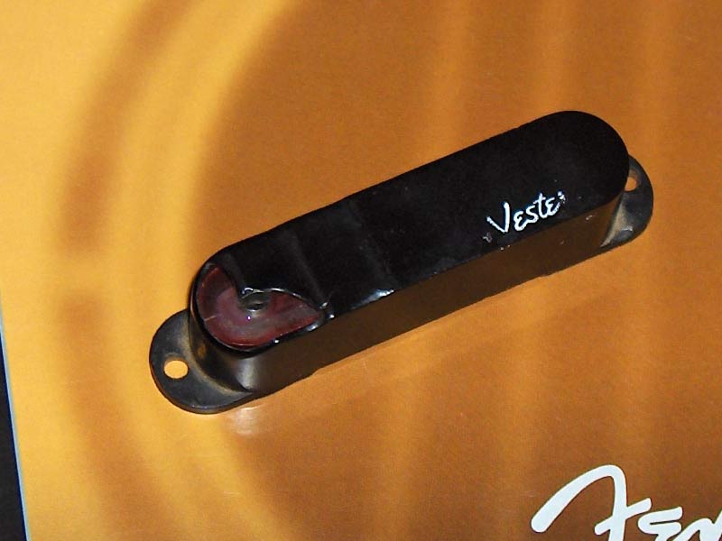
Strip the pickup and remove all wire. There’s a lot of very thin wire there so cutting it instead of unwinding is the way to go. In this case, pickup was potted which made stripping wire even harder. Nice thing about this is that pole pieces can be adjusted, so if I end up with uneven sustain I’ll be able to set poles higher or lower to compensate difference.
Step 2: modifying the bobbin height
Pickup coils are usually wound to around 10mm of height and bobbins are designed to fit a coil that’s 10mm high. For sustainer driver, optimal coil height seems to be around 3mm, which means that we need to modify the bobbin to limit coil height to 3mm. One way to do it is shown below.
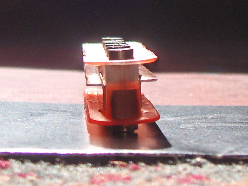
The way I did it was using a thin (around 0.5mm) piece of transparent plastic used for packaging that I bent into L profile and cut to shape with scissors. Then I glued it in place using epoxy glue. Super glue can also be used for quicker setting time.
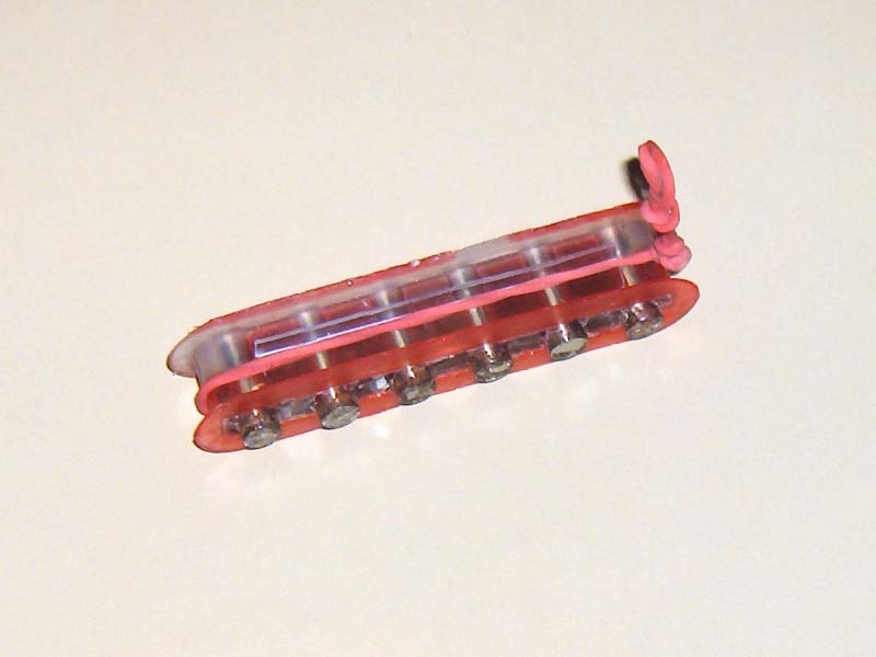
Step 3: winding the coil
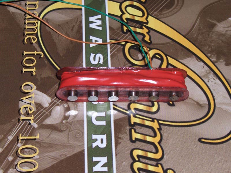
The recommended wire gauge for winding the coil is 0.2mm (AWG #32). Other gauges might work, but thinner wire will have less resistance, so it would take less turns to get to the target coil resistance of 8 ohms. With less turns we’ll have lower inductance, so our driver will be weaker. Other other hand, thicker wire has less resistance, so we need more turns to get to 8 ohms. More turns of thicker wire would make a physically large coil that might be too large to fit on a guitar pickup bobbin. 0.2mm is a good middle ground between physical size and number of turns needed to produce a coil with DC resistance of 8 ohms. Taking the resistance of copper into account, we can calculate that we need around 14.9m of wire to get the coil to target resistance of around 8 ohms. Using the calculator for estimating number of turns we get around 120 turns on a strat bobbin. It will depend on the geometry of the bobbin, so it’s best to check coil resistance as you go. I used transparent universal glue to pot the pickup after each 20 or so turns to make sure the coil is kept in place and to prevent microphonics.
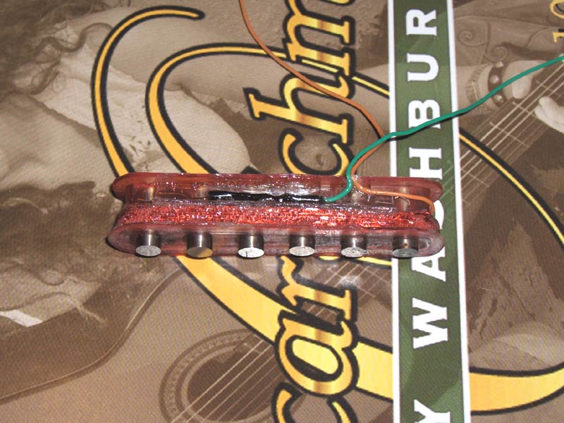
After 100 or so turns you can try to take the insulation off a tiny portion of the wire using a knife and measure the resistance of the coil so far. If you reached 8ohm, it’s done. Otherwise, do a layer or two more and repeat until you get to the target resistance. When it’s done, I soldered leads to both ends of the coil, secured them with a blob of glue and covered everything with insulating tape.
Step 4: the circuit
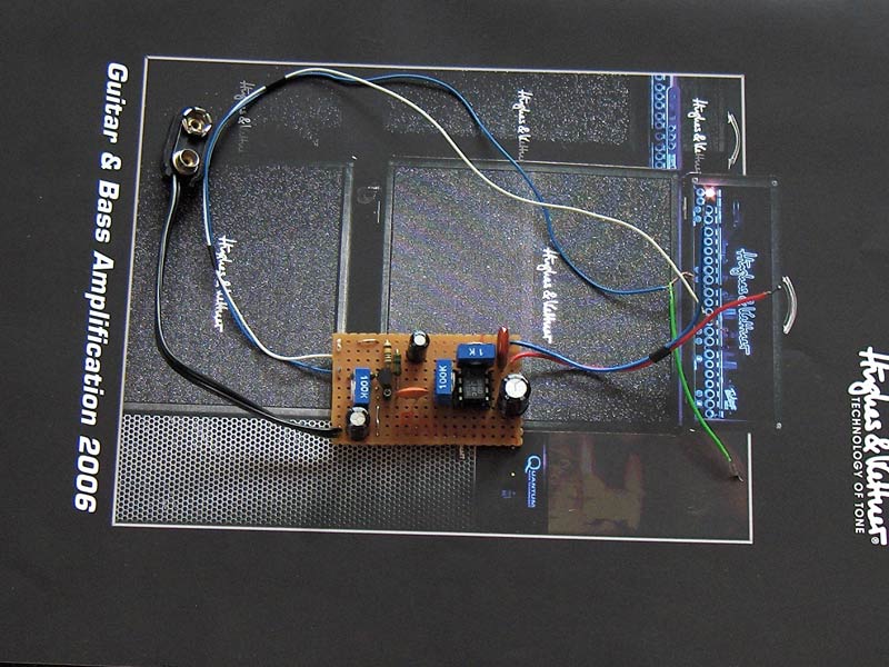
For the circuit we want to build a real clean guitar amplifier that operates the same way as a conventional amplifier, but instead of driving a speaker, it drives our sustainer. Pretty much any amplifier that can deliver few hundreds of milliwatts of power can do the job. A few people have reported Fetzer/Ruby amplifier from ROG to be performing well, so I decided to use that circuit. It’s got one FET gain stage (Fetzer Valve booster) that amplifies input signal before it hits the LM386 power amplifier taken from Ruby amplifier circuit. Both circuits may be found at runoffgroove.com and it’s just a matter of putting them together. I used trimmers for all controls and omitted Ruby volume control, as we already have one in the Fetzer Valve part of the circuit. 100K bias trimmer on the FET should be set to position that gives us roughly 4.5V at the drain of the FET and the remaining two trimmers should be adjusted at the end when the driver is installed in the guitar.

For my build I used this simple but not very compact perfboard layout. I suggest building as small board as possible, increasing the chance of fitting it inside the guitar without the need for routing.
Step 5: wiring
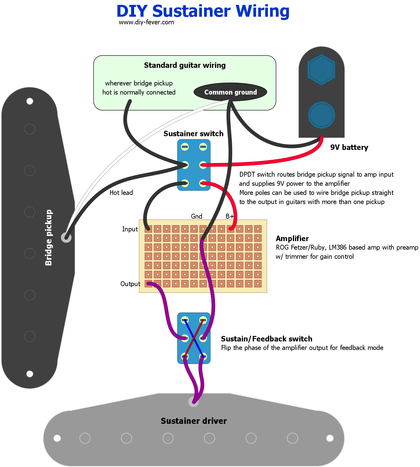
By popular request, I updated the article with a proposed wiring for the sustainer driver and circuit. I don’t have ability to test now it as it’s been almost 10 years since I built the sustainer, so if anyone does try it, please leave your comments below. There’s more than one way to do it and it will depend on your guitar. It’s ideal to have only bridge pickup and sustainer in the guitar because it will reduce a chance of interference between the driver and other pickups. Driver emits a lot of EM waves that excite the strings, but other pickups can pick them up too, and that’s not good!
Sustainer can operate in two modes: in phase which amplifies vibrations of the strings making them sustain indefinitely (or as long as the battery has enough juice to power the circuit) and out of phase (harmonic) which makes the guitar feedback with harmonics (listen to some of Steve Vai live performances, like “Building the Church”). The two modes can be toggled using a DPDT switch that flips the positive and negative side of the amplifier output.
As for the main sustainer switch, there’s more than one way it can be wired and in some cases you may need 3 or 4 pole switch. This is the simplest implementation that kills the battery supply to preserve power and when engaged it wires bridge pickup to the amplifier.
Step 6: tweaking
After the driver is installed in the guitar, we need to tweak the Gain and Volume trimmers to make sure that we get enough sustain but not get into feedback and oscillation. I suggest starting with both trimmers around noon and tweaking it from there. We are aiming for infinite sustain that doesn’t increase the level or add distortion. In sustain mode, if you hit the note and it starts amplifying on its own until it goes into oscillation, it means that Volume and/or Gain are too high. On the other hand, if there’s no infinite sustain, we should increase Gain and/or Volume.
Like with the pickups, the driver height will affect how it performs. The closer it is to the string, the stronger it will affect them. Using the same height as a typical guitar pickup is a good starting point and you can tweak it if there’s need.
Useful links
Project Guitar "Sustainer Ideas" thread (very large)
Project Guitar tutorial on building driver
Program for calculating number of turns for given core dimensions and wire gauge
Official Fernandes Sustainer page

")
")
![Deep Purple - Lazy [Guitar Cover]](https://i.ytimg.com/vi/7ZyjTZgM2DY/default.jpg "Deep Purple - Lazy [Guitar Cover]")
")
are this really works ?
I doubt it ….
really I’ve trying to build but it doesnt work
could you please give me the wiring include instruction of winding pick up ???
hello, my sustainer does not work on strings g, b and e or on the wire strings. In fibrous strings does not matter. Any suggestions for this problem ….
thank you, but why the sustainer only work with bridge pickup. Sorry for my bad english
You’d run into noise issues if used with the middle pickup because of proximity to the driver
my sustainer working on E string, A and D but the strings g, b, e the sustainer does not work at all. I just use a simple LM386 preamp but do not use a FET transistor. Whether it is the cause. Thanks …
thanks for your tutorial. but im still confusing about how to install or connect my guitar to sustainer and the driver sustainer pickup. Please see my pic diagram http://i1188.photobucket.com/albums/z407/viantd/pepi_sustainer.jpg. if my pic wrong, tell me or email me a right schematic diagram. thanks again for your hel..
Hi,
the diagram isn’t correct. The sustainer does not stand between your guitar and amp, but rather branches into another signal path. It’s effect on sound is through the driver.
You need a 3PDT switch that does the following when ON
Hope it makes sense,
Bane
I allready follow all instruction well, but the sustainer dont work at all,
i used ruby amp ,
for the pickup how many ohm
could you please send me the diagram and winding proccess
thanks
Hello!! the scheme where you are? thanks!
Hi, firstly, thanks for really quick answer 😉 Next, I still have problem – I’ve been trying a lot of possible solutions. Swapping leads should only affect in switch between normal and harmonics (I pluged them into the DPDT switch), so I don’t think it’s a problem. To much gain – I have an amplifier without gain or volume control, so I pluged potentiometer before amplifier, then I tryied after amplifier, before driver. Now I’m able to keep sustainer working in almost every point of the string, close enough to put it in the hole, but it just stop working when I turn it upside down and put in the hole. When I give big gain, I have constant noice as before, with lower gain noice stops, but sustainer doesn’t work. Any idea? Greetings.
Hi, I’ve almost made my sustainer but I still have some problems. When I’m testing my driver over the neck (up to 24th fret) it’s working great. It stop work when I move it closer to the hole prepared for it (ex-neck pickup hole). Next, when I turn it upside-down (magnet down) and place it in the hole, it starts to generate some kind of noice, not depending on what I’m playing etc. It sounds like very high feedback. Can You help me with this? I’m affraid my driver has a bit to low resistance (about 7.1 Oms), but I can’t place more wires in 3 mm of space, should I make a bit larger space and force it to has 8 Oms? Thanks in advance 🙂
don’t worry about impedance, 7.1 is close enough. Try to swap driver leads and see if that solves squeal.
Cheers
another thing, try to reduce gain in the circuit if swapping leads doesn’t help. It’s possible that you have too much.
does this sustain on the top b ande strings..especially on the higher fret notes?…12-21 fret?…
Hello I was wondering if you could be a bit more specific about the parts needed for this sustainer.
I’m ordering a lot of them online but when I, for example, am looking for a 47n Capacitor they vary a lot. There is for example a capacitance tolerance and voltage rating. Or should i just look for everything with voltage around 9-12 V?
I hope to hear from you soon!
most common film capacitors in nF range are rated 63V, those will work fine. As for tolerance, shouldn’t matter.
cheers
hi,
which wire goes to the output nob??where the sustainer on/off switch should i connect??
regards,
Atif amin
Hi!
I have two questions but first I want to congratulate you on simplifying things 🙂 I wonder how does your high e string sound, is it sustained on high frets and the other is what kind of magnet did you use?
cheers,
vladimir
hey, can I see the wiring???
please explain it with pictures
hey dude, can I see the wiring????
please explain it with pictures
Hi. . I already made the fetzer ruby. . .but i dnt know how to instal it to the guitar wid hss c0nfig and a 5way switch. .can you send me a diagram? Can i substitute a push pull pots for the switch? Thanks dude
Is it works with chords? Can it provide sustain with several strings?
If you had read one of the sites that are linked above, you would know the answer: NO!
how does this sound (regular sustain/harmonic mode) against a sustainiac or fernandes?
I have Ibanez JEM with DiMarzo pickup.
I guess I have to remove the neck evolution pickup and replace it with piezo coil
I already understand how to make piezo and driver fetzer/ruby
the pickup wiring diagram is standard HSH.
how the wiring diagram to install fetzer/ruby driver to my guitar.
the fetzer/ruby circuit diagram i found it at your DIY software
what is the scheme? I mean where the wire goes from driver to pickup/5 way switch?
can u draw and send it to my email?
thanks for the great job
Thanks for this! A few questions though…
1. No thoughts on how well it worked?
2. How did you wire it to the guitar?
Hi,
nice job!
Where does the driver pickup is connected?
Looking at your driver, i try to guess 🙂 orange and green wires connects to the blue and white,and then ?
I’m really frustrated 😀 please help!
Thank’s
Bye
Hi,
orange and green would go to red and blue on the right side of the board. That’s the output of the amplifier. In between you will probably want to have a DPDT switch that changes polarity (green to red, orange to blue and the other way round). That way you’re changing between sustain and harmonic modes.
Cheers,
Bane
Thank you very much!
And what about white and blue wires? I have a dual humbucker guitar with 4 knobs (gibson like), my idea is to replace neck pickup with an 8 ohm “single coil” driver (even if the hole) … should white and blue wires have to be connected where the old nec kpickup was?
One more time, thank’s!
nope, blue wire goes to guitar ground and white goes to the bridge pickup output. You will also need a switch to turn the sustainer on and off, probably the best way would be to cut the voltage out.
Hello,
Thanks for your work in the sustainer proyect.
I would like to make one, but i need instructions and info to start, where i can find information to do the circuit and coil/magnet?
Regards,
Gabriel.
Hi,
the circuit is Fetzer/Ruby (you can find it on http://runoffgroove.com/). As for the coil, check out the photo gallery on this page. There’s description under each photo. Also turn calculator program I referenced under links will be helpful…
Cheers,
Bane
i need the wireing diagram to know how to wire all the peases on the board i dont see the layout .. thanks