JohnH M2 Attenuator
Introduction
If you’ve followed my previous posts, you know by now that I’m absolutely obsessed with getting great tube tones at bedroom volume. Most of the time, I only get to play late at night while my family is sleeping, so keeping the decibels down is a massive priority. My strategy up to this point has been to use exotic power tube options to squeeze very low wattage out of the power amp stage—though honestly, even that often ends up being too loud anyway. Having been out of the amp-building loop for a couple of years, I was super excited to discover the JohnH M2 attenuator, which is highly praised online for being incredibly transparent and fully capable of bringing roaring amps down to reasonable room levels. It inspired me to rethink the strategy for my most recent build (the awesome Hairy Pink Taco V2) and go straight for the full-scale 20-watt version of the circuit, fully trusting the attenuator to tame the beast.
Features
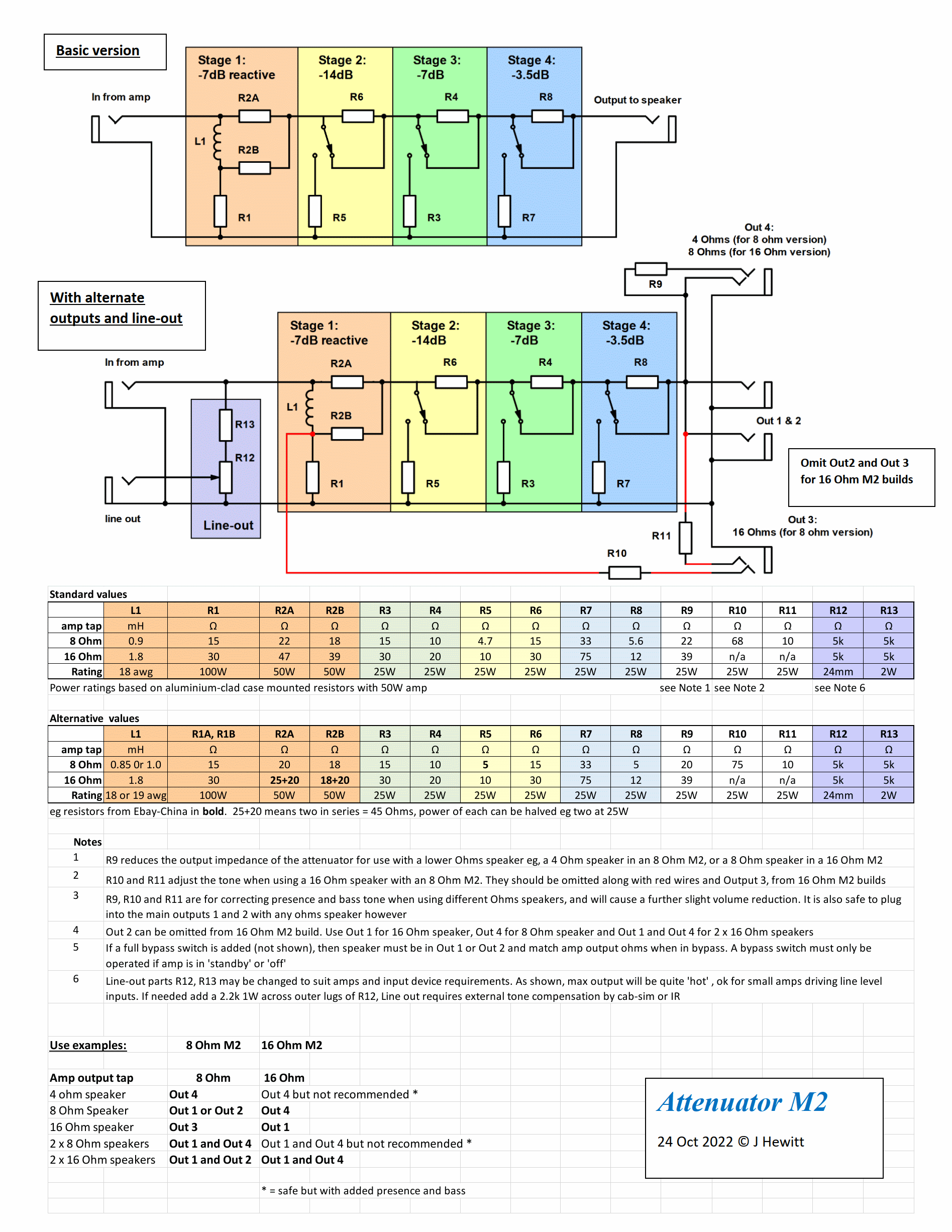
The base version of the attenuator is brilliantly simple, yet incredibly effective. Instead of relying on the more common continuous volume control using a massive L-Pad or a rheostat, the M2 opts for a much more elegant, fixed-step approach. It’s built around a multi-stage design consisting of four total attenuation sections. The first stage is fully reactive and always engaged, knocking the output level down by a base 7dB. It relies on the inductor to present a dynamic, impedance-accurate load to the power amp that closely mimics how a real speaker coil behaves. The remaining three stages are switchable and purely resistive. When engaged, they drop the volume by an additional 14dB, 7dB, and 3.5dB, respectively. These stages can be freely combined, offering an impressive maximum volume reduction of 31.5dB.
The design also allows for a few optional features, like a dedicated line-out and additional parallel speaker outputs. I decided to include the line-out circuit, as having a tapped signal is super useful for direct recording or running into impulse responses. However, I didn’t really have a need for multiple speaker outs in my specific home rig, so I just skipped them to keep the build clean and straightforward.
The Circuit
Below is the original schematic with some useful notes by the author himself, reposted with the permission.
Sourcing the Inductor
My initial plan was to go full DIY and wind the inductor myself, despite having absolutely no prior experience with it. I picked up some 1mm (AWG 18) wire and 3D-printed a couple of custom bobbins to tackle the job at home. However, without a proper winding rig, getting consistent, tight turns proved to be much more difficult than I had anticipated. Both of my attempts to hit the target 0.9mH value failed due to sloppy, inconsistent winding—filling up the bobbins completely but only yielding a measurement of around 0.7mH. I quickly changed course and just ordered a professionally wound 0.9mH coil off the shelf, which hilariously ended up costing even less than the raw copper wire I bought for my failed attempts!
Scaling Down
The original M2 circuit is designed to handle amps up to 50W, which is far more than I need — I honestly don’t see myself ever running anything over 20W. To optimize for enclosure size, component availability, and overall cost, I decided to scale down the power ratings on the resistors while still maintaining a healthy safety margin for a cranked 20-watt amp. I left the inductor spec exactly as called for in the original schematic, since downsizing it wouldn’t have yielded any real space/cost savings anyway. For the resistors, I went with a robust 50W rating for the critical R1 position, 5W ceramic resistors for R3/R5/R7 and 25W components for the rest of the network. This scaled-down footprint fit my chassis perfectly while still providing plenty of thermal headroom for complete peace of mind.
Layout
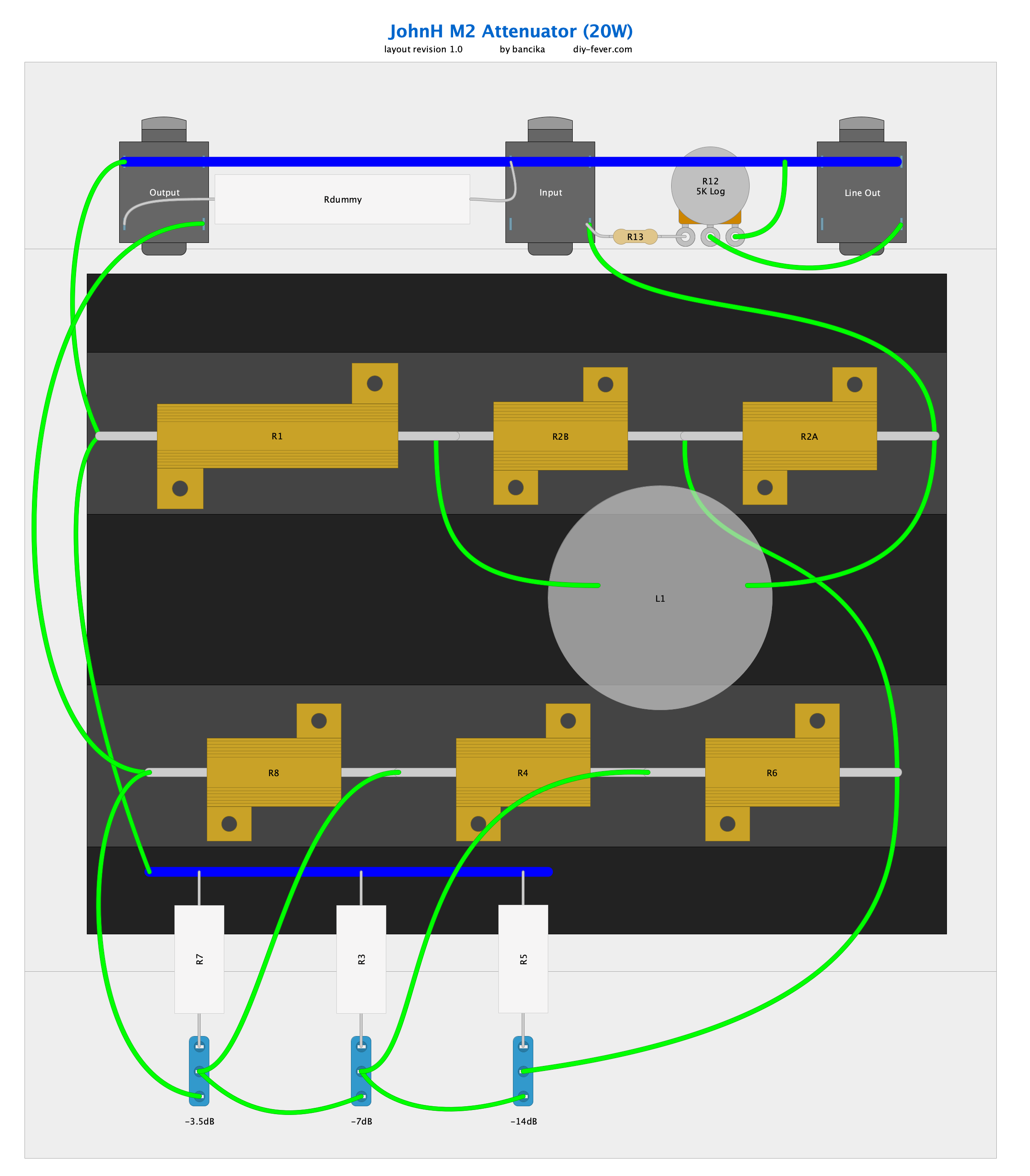
I’ve had a blank chassis sitting around for years just waiting for the right project, and it turned out to be the absolute perfect size for this build. It features a really convenient design with two internal rails holding everything together, meaning any of the four panels can be removed independently for easy service access. While that’s great for maintenance, it actually makes it a bit harder to mount the heavy power resistors directly to the chassis, and the smaller individual panels provide very little thermal mass for cooling anyway. To solve this, I hunted down a massive, dirt-cheap heatsink salvaged from some old medical equipment on the local classifieds. After a quick trim, it dropped perfectly into the enclosure. Not only does it provide incredible heat dissipation, but it also gave me a solid, centralized surface to physically mount all of the aluminum-clad power resistors. It has two rows of flat surface wide enough to host several TO-3 devices each which coincidentally is perfect width for power resistors as well. The remaining 5W ceramic resistors are simply point-to-point wired and suspended in the air.
Build Photos
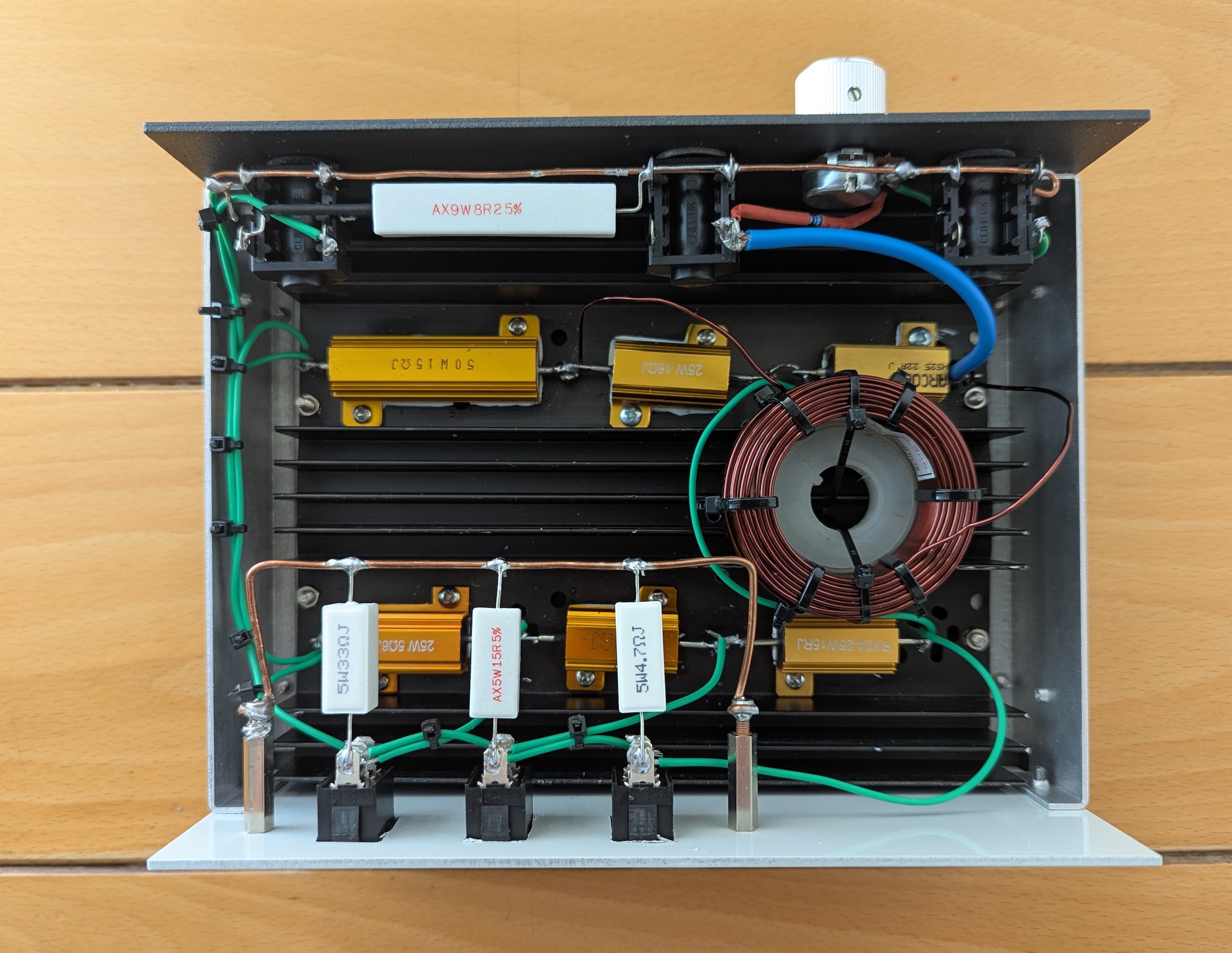
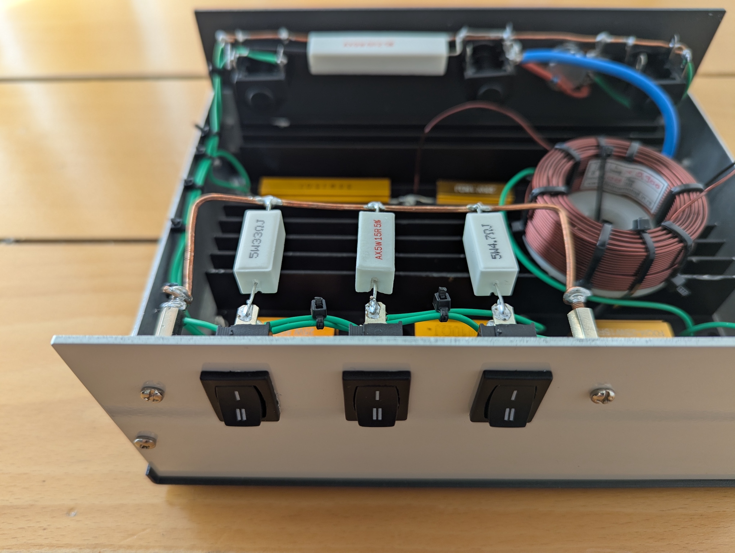
I did not photograph the entire build process as it’s relatively simple, so below are the photos of the finished project.
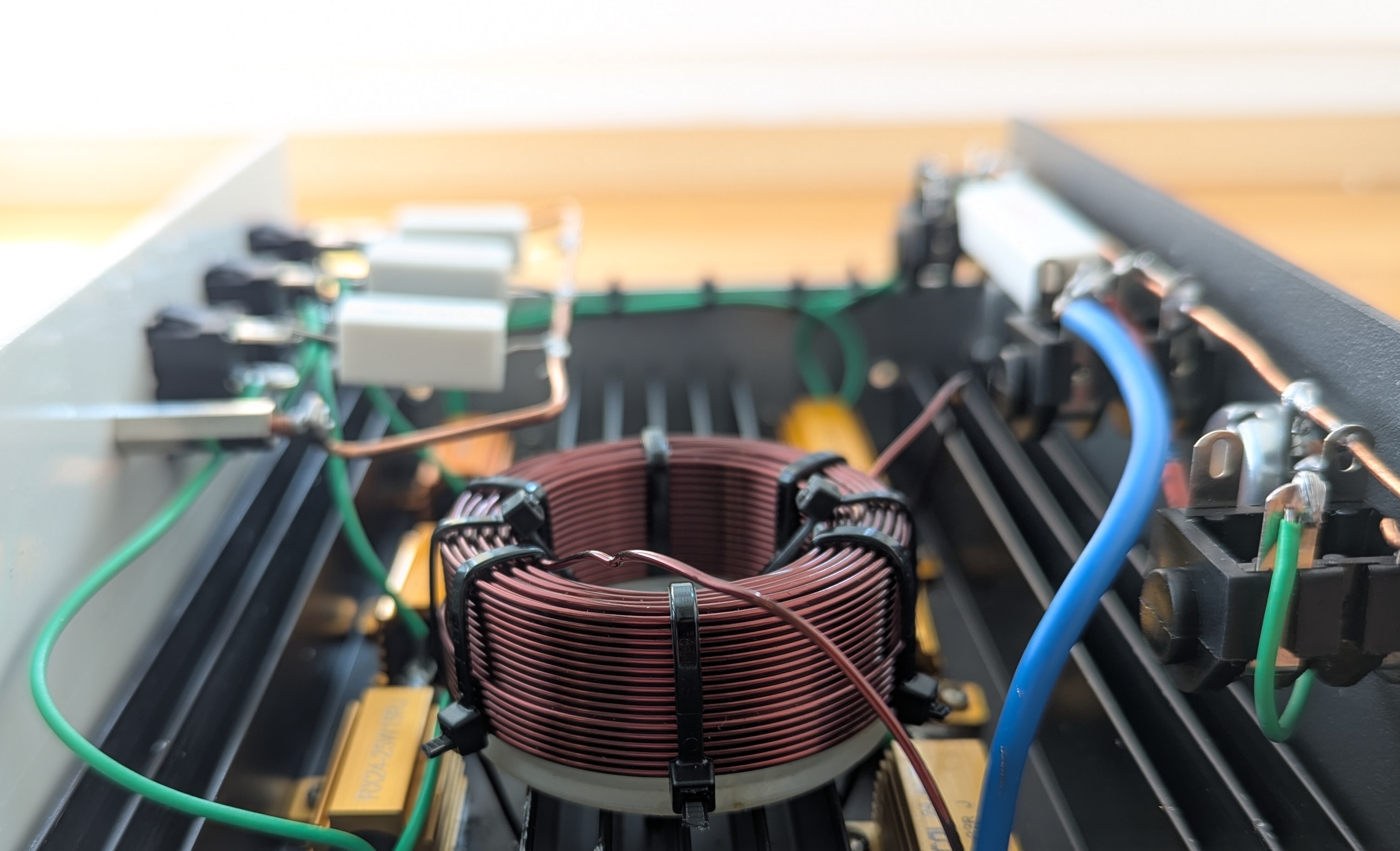
The inductor is securely mounted using cable ties, following the design recommendations to avoid using any metal hardware that might interfere with its magnetic field. To provide some necessary physical clearance between the copper coil and the aluminum heatsink, I actually repurposed an empty solder wick spool. It features one flat side and one conical side, and it coincidentally matched the inner diameter of the inductor perfectly, making for an absolutely ideal, makeshift spacer.
For the attenuation controls, I went with those standard plastic rocker switches, which unfortunately require rectangular panel cutouts. As any DIY builder knows, cutting those out by hand is an absolute pain with the basic metalworking tools I have at my disposal, but with a little patience and careful filing, they actually turned out looking pretty clean. The photo below also highlights the solid copper ground bus I fabricated to neatly tie together the three ceramic resistors running directly off the switches.
Learn More
To the best of my knowledge, the closest thing to an official M2 project page is an incredibly detailed, long-running mega-thread over on the Marshall Forum. It kicks off with the original post breaking down the core design and is followed by dozens of pages packed with absolute gold—invaluable insights, tweaks, and build reports from the creator himself, as well as a huge community of folks who have successfully built it.
![John Petrucci - State of Grace [Guitar Cover]](https://i.ytimg.com/vi/K3bYjMICR5g/default.jpg "John Petrucci - State of Grace [Guitar Cover]")
![Dream Theater - Spirit Carries On [Guitar Solo Cover]](https://i.ytimg.com/vi/0IXe-W7Ca-Y/default.jpg "Dream Theater - Spirit Carries On [Guitar Solo Cover]")


