(Hairy) Pink Taco V2
Introduction
I took a bit of a break from building right around the time the kids came along. It’s just how it goes; when you start a family, hobbies are usually the first thing on the chopping block. But after a few years of plugging into a Yamaha THR-10X — which is honestly a great little desktop amp for what it is — I started feeling the itch to build something new. I hadn’t built anything or bought anything in years, and truth be told, I’d become totally immune to gear review videos. 🙂 But then, I accidentally stumbled upon some of the newer 20W Friedman lunchbox heads and was absolutely blown away by the demos. It was the exact sound I’d been chasing in my head all these years.
In recent years, I totally rediscovered Van Halen and got deep down the rabbit hole chasing the legendary “Brown Sound.” My trusty old THR-10X definitely helped fuel that fire, featuring some really great emulations of BROWN I (early EVH) and BROWN II (later EVH) that became my absolute go-to patches. Over time, my ideal tone benchmark completely shifted away from that ultra-thick, layered, Petrucci-esque liquid lead sound toward something a whole lot more raw, open, and aggressively tight. My modern tonal holy grail is essentially EVH meets Slash, meets Blackmore, meets Satriani, meets Vai, with a splash of Nuno and Cantrell. When you look at those players, they all have one major thing in common: hot-rodded Marshalls at least in some point in their careers. In fact, several of them are famous for using legendary Jose Arredondo-modded plexis, which is the exact lineage and DNA that Dave Friedman’s designs lean so heavily into.

Dave Friedman is the modern-day authority on hot-rodded Marshall circuits, and he single-handedly managed to pull those legendary tones out of the underground modding scene and bring them to the mainstream. Let’s be real — his amps aren’t exactly cheap. But unlike those totally unobtainable, mythical “unicorn” Jose Arredondo amps of the past, Friedman heads are modern production pieces. They are well-engineered, built to handle life on the road, and readily available to anyone chasing that ultimate high-gain plexi roar.
When I first started building amps and pedals way back when, it was strictly out of necessity — I simply couldn’t afford the gear I wanted. And often times what I needed didn’t even exist. Low power amplifiers at the time were typically crappy entry level models. Fast forward 20+ years, and while I can thankfully afford to just go out and buy a factory Friedman now, that classic itch to build cool and unique stuff with my own two hands came roaring back. And let’s be honest, so did the itch to take a stock design completely over the top. One thing led to another, and before I knew it, I was ordering the PI18 kit from Tube-Town, which is heavily inspired by the V1 Pink Taco circuit with just a few minor tweaks, knowing in advance that I will tweak it further.
While I was doing my homework on the amp, I realized that the V2 of the Pink Taco circuit brings some really great updates to the table. On paper, it definitely sounded like the version to build. The catch? There wasn’t a ton of documentation out there, and the Tube-Town kit comes with a PCB designed strictly around the V1 layout. Luckily, an awesome member over on the SloClone forums shared some incredibly detailed gut shots of a V2 unit, and another member had already made a decent attempt at tracing it. After watching a bunch of interviews with Dave Friedman explaining exactly what he changed for V2, doing my own deep-dive trace from those forum photos, and even asking Dave to confirm my doubts (which he did!), I managed to spot a few mistakes in the original community V2 schematic and fix them up.
Simultaneously with the V1 vs V2 rabbit hole, I was also deep into researching hot-rodded Plexi circuits and popular mods. I couldn’t help but wonder what else I could tweak to take the V2 design to the next level. If I was going to fire up the soldering iron again, I wanted to build something truly unique and absolute ass-kicking.
Volume Concerns
If you’ve followed any of my previous work, you probably know by now that one of my absolute biggest goals is achieving massive tones at bedroom-friendly volumes. I don’t gig or rehearse with a band, and the vast majority of my playing happens late at night when everyone else is sleeping. Being able to dial in those cranked, full-bodied sounds at TV levels—while still pushing the amp’s circuit hard enough to get the goods—is absolutely crucial for me. Make no mistake, a 20-watt tube amp is blisteringly loud by home standards, especially when pushed through a highly efficient speaker. Although I have a custom 1×6″ cab loaded with a Jensen C6V that does a decent job keeping things manageable, I was really craving more low-end thump and a much fuller overall sound. So, I picked up a Harley Benton Thiele cab loaded with a Celestion G12M-65 Creamback (ridiculous value for money) which should be close enough to the Friedman 1×12″ Cab which carries the same speaker and similar Thiele design, but at one third of the price of the Friedman. It sounds absolutely huge and incredibly rich, but naturally, it’s also a whole lot louder. To tackle that volume issue, I put together a JohnH M2 Reactive Attenuator during the initial planning phase of this build, treating it as a bit of a warmup project before diving into the main amp. The goal was to heavily knock down the decibels while retaining all the punch, dynamics, and feel of a cranked output section.
Schematics
Below is the preamp schematic that I traced.
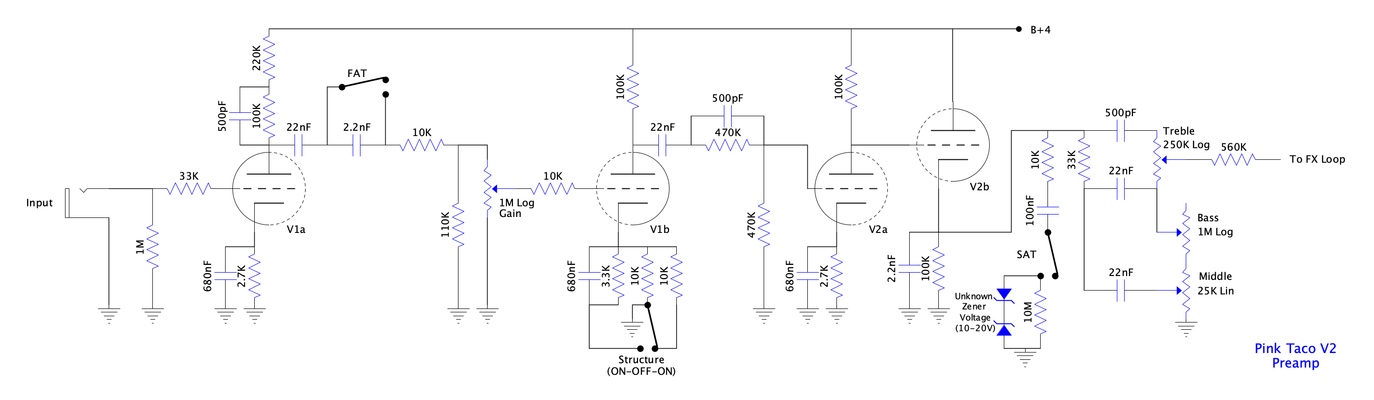
Power amp and power supply schematics are pretty much redraws of available PT20 v1.3 schematics from SloClone Forum. One change I made is to adjust the output cathode resistor which was increased from 120ohm to 130ohm between versions 1.x and 2.0 of PT20, biasing the output tubes slightly less hot. PI18 kit takes it a bit further but more on that later.
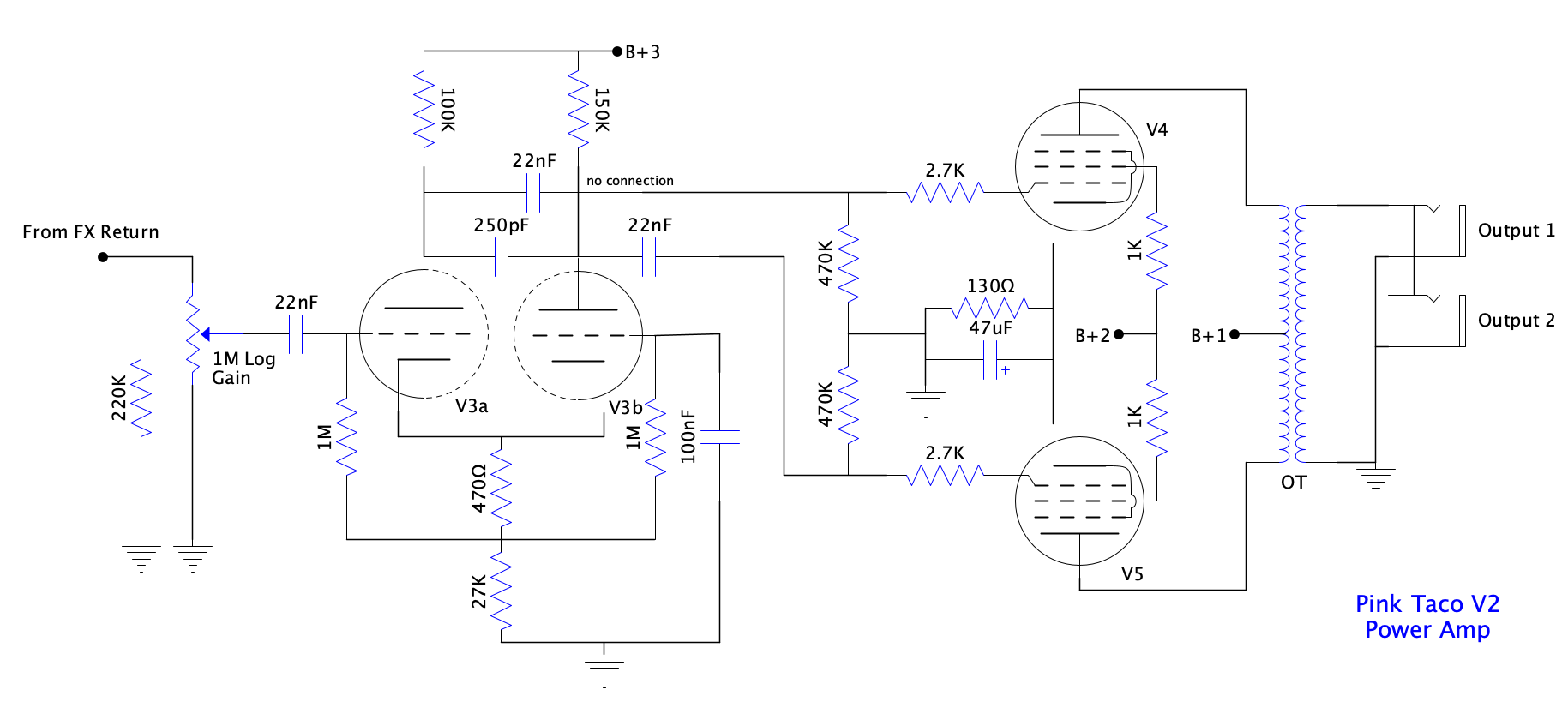
PT20 V1 vs V2
So what has changed between versions 1.x and 2? With V2, Dave addressed a common complaint about PT20 V1.x being too dark sounding. Also he expanded on the gain range and included some of his most popular mods that add a lot of versatility and tonal options to a single-channel amp.
Structure Switch
Technically, the structure switch started popping up in later revisions of the V1 Pink Taco, while earlier versions had no switches at all. In essence, it toggles between three different cathode resistor and capacitor combinations on the second gain stage, giving you three distinct levels of gain and voicing. Over the years and across different models, Friedman has used slightly different resistor values for these switch positions. In the PT20 V2, he uses an always-on 10K cathode resistor. Then, using an ON-OFF-ON toggle switch, the other two positions let you throw another 10K resistor in parallel, or switch in a 3.3K resistor paired with a 0.68μF cap.
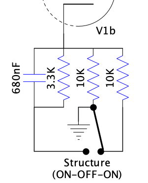
Center Position (Off)
- The Circuit: Configures the circuit with a 10K total resistance and no effective bypass capacitance.
- The Effect: The cleanest, most “open” setting with the most headroom, yielding a low-gain, vintage response.
Left Toggle (Medium Gain)
- The Circuit: Drops the total resistance to 5K with no effective bypass capacitance.
- The Effect: Increases the tube’s overall output. It sounds crunchier but stays “tight” and balanced since there is no bypass cap altering the frequency response.
Right Toggle (High Gain / Hot Rod)
- The Circuit: Drops the total resistance to 2.5K (close enough to the standard 2.7K Marshall-esque value) and introduces an effective bypass capacitance of 0.68μF (also typical for Marshall).
- The Effect: The highest gain setting. It saturates the tube heavily, giving the amp a classic “British” or hot-rodded “Plexi” bark.
- Frequencies Affected: The 0.68μF capacitor specifically boosts the mid and high frequencies, adding aggressive bite while keeping the extreme low-end from getting muddy.
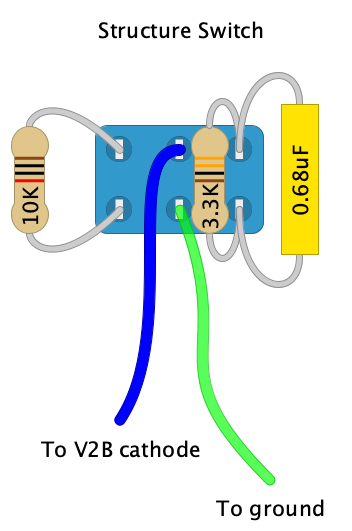
It is relatively easy to implement the structure switch in the PI18 circuit. The stock PCB expects a single 2.7K resistor and a 0.68μF cap on the V1a cathode. Instead of that 2.7K resistor, I dropped in the always-on 10K resistor, and then repurposed the eyelets intended for the capacitor to run a shielded cable out to the toggle switch. From there, the two remaining resistors and the capacitor are mounted directly on the switch itself. Just a heads-up, though—to make this layout work cleanly, I had to flip the components for the V1a and V1b cathodes. On the stock PI18 layout, the V1a components are board-mounted, while the V1b cathode components sit right on the tube socket using a mini tag strip. To simplify the wiring for the switch, I decided to mount the V1a cathode components on that tag strip instead. This freed up some prime real estate on the PCB, giving me plenty of room to comfortably mount the 10K resistor and the leads heading out to the structure switch, while avoiding any compromise on the sound quality or noise.
Saturation Switch
The circuit here is pretty much the same one you’ll find on other Friedman amps. It injects a totally different character of distortion thanks to diode clipping, making it an awesome addition to the build. Typically, Friedman uses MPSA06 transistors for the saturation circuit in the BE amps, but for the PT20 V2, he switched to Zener diodes. I don’t know the exact voltage of those stock Zeners, but it’s definitely worth experimenting with values in the 7-20V range, since that’s what you usually see in similar high-gain circuits. Lower voltage Zeners will clip the signal earlier, making it compress more, while higher voltage Zeners will let the signal breathe a bit more before clipping. The key is striking a good balance—you want enough contrast to give you a fresh distortion flavor, without overdoing it and turning the tone into a compressed, fizzy mess.
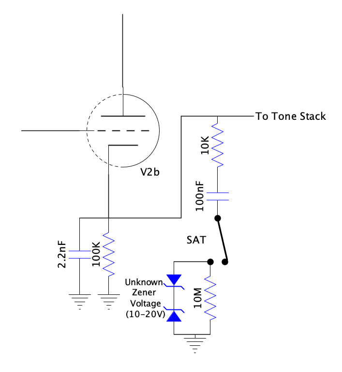
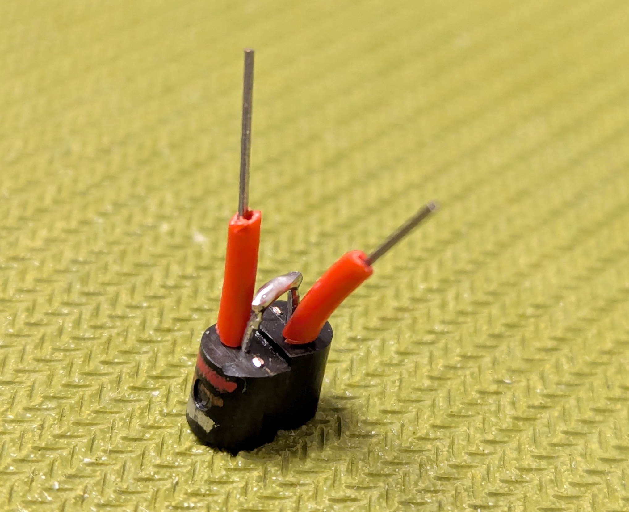
I decided to go with the tried-and-true MPSA06 transistor trick, but I could only source the PNP equivalent locally — the MPSA56. They are electronically equivalent, just complementary. For the sake of the clipper circuit, the polarity does not matter. While the MPSA06/MPSA56 datasheet specifies an emitter-base breakdown voltage of just 4.0 volts, every single one I had on hand measured noticeably higher when tested as a Zener between the emitter and base—clocking in around 7.5V. When you wire two of them back-to-back in the clipping circuit, you’re effectively putting the base-emitter junction of one transistor in series with the emitter-base junction of the other. This applies to both sides of the waveform. One transistor acts like a ~7.5V Zener, and the other acts like a standard 0.6-0.7V silicon diode. Together, they clip the signal right around 8V, which hits the sweet spot perfectly.
It is worth mentioning that while this circuit is inspired by the legendary Jose diode clipping mod, it’s actually a bit different. It’s more subtle and introduces asymmetrical clipping into the mix. Jason from Headfirst Amps did a killer side-by-side analysis of the two circuits, and I highly recommend checking it out if you want to see how they compare. The hybrid solution that he proposed sounds a bit more aggressive to my ears, which I know a lot of players would love. However, I felt like the standard Friedman circuit would give me plenty of variety and saturation on its own. Plus, adapting that hybrid circuit to the PI18 PCB would have meant moving a few other components around the board, so I stuck with the standard Friedman circuit instead.
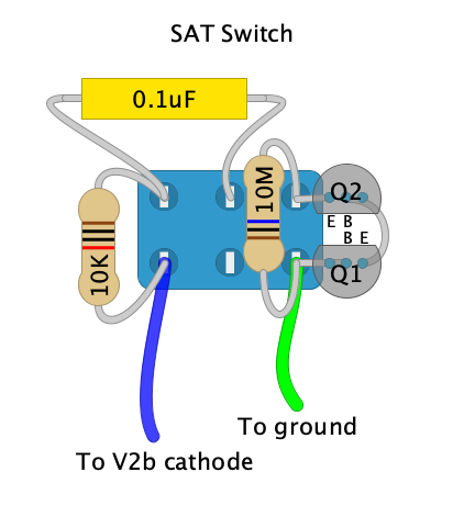
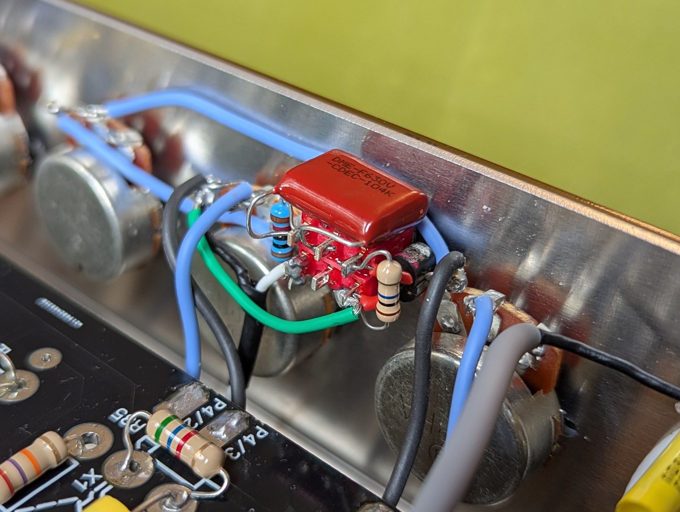
Just like with the structure switch, I decided to mount all of the components directly onto the toggle switch itself. This time around it’s a bit more tricky since there are a few extra parts to juggle. It’s awesome not having any “floating” components hanging off the wiring, but it does result in a pretty hefty switch assembly. I definitely underestimated just how big it was going to get once all those components were soldered on, and I could barely squeeze the whole thing into its planned slot on the chassis between the treble and middle pots.
Fat Switch
Just like on other Friedman amps, this switch lets you toggle between a ~2nF and a 22nF value for the first coupling capacitor, which effectively shifts your low-end roll-off point. With the ~2nF cap engaged, it cuts everything below roughly 80Hz—which is pretty much the frequency of a low E string on a standard 6-string guitar. Flipping it over to the 22nF “fat” mode pretty much lets all the low end through, leaving the rest of the circuit to handle the filtering. This is super handy for single-coil guitars that are naturally a bit lean on the bottom end and can’t afford to lose any bass without sounding thin. Ultimately, I decided to skip this mod entirely. I don’t really need it, and I wanted to ration the number of toggles on the front panel—every extra switch means more unnecessary wiring and a higher risk of introducing noise or oscillations into the build.
Top-end Response Tweaks
A few people have mentioned that the V1 circuit can lean a bit too dark (and I’ve heard the exact same complaint about the stock Tube-Town kit). To fix this, the V2 circuit removes a few of those treble-cutting caps or reduces them in value. The result is a much-improved high-end response that opens up the amp without making it sound harsh or shrill.
Gain Control Improvement
The gain pot was also moved from its spot after the second stage to right after the first stage, which drastically improves the overall gain range. When the gain control is too far down the line, there is no way to attenuate the signal hitting that second stage, meaning it will always overdrive hard. By moving the pot earlier in the circuit, we can clean up the signal hitting the second tube and dial in a much cleaner edge-of-breakup sound if we want it. Don’t worry, though—you don’t lose any gain this way. On the contrary, Dave tweaked the values of the first voltage divider network to a 10K series resistor and 110K to ground, instead of the old 68K/68K setup. This means when you max out the gain pot, there is noticeably more signal hitting the second stage than before, giving you even more glorious distortion.
In the context of the PI18 kit, moving the gain pot one stage earlier requires a few changes, but nothing major. First, we need to jumper the original P1/1 and P1/2 holes on the PCB. Since we aren’t using the pot in its stock location, we want to bridge that gap so the full signal passes right through. Next, we feed the input of the gain pot from the PCB hole on the output side of that 10K voltage divider resistor on the first gain stage. Finally, from the wiper of the pot, we run a shielded lead straight to the tube socket, where a new 10K grid stopper is mounted right on the tag strip. Beyond just getting the pot where we want it in the circuit, this layout tweak actually helps out in the noise department, too, since direct-mounted grid stoppers offer much better protection against unwanted noise and oscillations. This also required drilling a hole next to the socket to mount the tag strip.
Partial DC Heaters
To keep the noise floor as low as possible, V2 introduces a DC heater supply for the first two preamp tubes. It uses a super simple circuit to get the job done—just a basic bridge rectifier followed by a C-R-C filtering network. It’s an easy addition that pays massive dividends in keeping unwanted hum out of a high-gain beast like this.
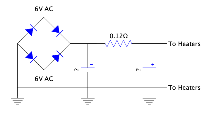
I’m not entirely sure what capacitor values the factory layout uses here, but given that the resistor sitting between them is a very low value, I’d guess you’d need at least 4700μF or even 10000μF caps to keep the AC ripple under control. For my own build, I did decide to go the DC heater route, but I took a completely different approach to it — more on that a bit later.
Tube Town PI18 Circuit Nuances and Tweaks
I can’t share the Tube-Town PI18 schematic or layout diagram here since it’s only provided to folks who buy the kit, and I want to respect that. However, I can confirm that it’s mostly based on the early PT20 V1 circuit that didn’t include the structure switch. The Tube-Town website lists the improvements they made to the circuit, so let’s expand on those a bit.
Noise Gate
The PI18 includes a basic noise suppression circuit using a few silicon diodes inline with the signal right after the master volume. This only allows the signal to pass through if it’s above the cutoff voltage of the diodes. I decided to skip this entirely — it’s just a matter of choosing whether or not to solder those diodes onto the PCB anyway. Personally, I tend to avoid noise gates because they can totally kill your sustain.
Master Volume Improvement
A 1nF capacitor was added in parallel with a 560K series resistor, immediately followed by a 22nF coupling cap. This filtering network sits right in front of the master volume control. It functions a lot like the classic 500pF treble peaker cap wired across the 470K resistor between gain stages one and two—effectively bypassing the resistor for higher frequencies to open up the overall top-end response of the circuit. I initially kept this modification in place because it sounded good with the FX loop completely bypassed.
However, once I started actually playing with the FX loop engaged, I noticed some severe tone degradation. All of the amp’s natural, punchy fullness just vanished, leaving the tone feeling overly tight, thin, and completely lifeless. I wasted a ton of time tweaking and troubleshooting the loop circuit itself, totally convinced it was the culprit. As it turns out, the way the loop’s output stage interacts with that specific pre-master filtering network was aggressively shelving all of the bottom end. Once I ripped that network out and reverted straight back to the stock Friedman master volume arrangement—running just the standard 220K reference resistor—the dreaded tone suck completely disappeared and the amp roared right back to life.
Voltage Divider Tweaks
Friedman uses some pretty unique, almost controversial resistor values on that first gain stage. For one, the combined plate resistance is unusually high (220K+100K). On top of that, the 68K/68K voltage divider in the PT20 V1 circuit (or the 10K/110K setup in the V2) following the first stage presents a fairly heavy load on that first triode. The PI18 circuit increases those values significantly to reduce the load and boost the output of the first stage. However, I believe Dave Friedman chose those stock values for a reason, sacrificing a little bit of output (there’s plenty of gain on tap anyway) to keep the low end tight and let the highs cut through. By going with significantly higher values like the kit does, you get a lot more output, but you also dump a ton of extra bass into the first stage. At the same time, it heavily increases the Miller effect on the second stage, which eats away at those precious frequencies above 3.4KHz. I didn’t want to risk a muddy tone, so I chose to stick with the Friedman values from the V2 circuit.
Pull Boost Switch
The stock kit uses a push-pull pot to drop some resistance in parallel with the lower resistor in the interstage voltage divider, letting more signal pass through when you pull the knob. This makes total sense in the context of the V1 circuit, but not so much for the V2. Since the V2 moves the gain control to that exact same spot, you already have continuous control over the signal level hitting the second stage. I ended up repurposing that push-pull pot for a bright switch instead, which we’ll get into below.
Low/High Inputs
Similar to some classic Fender circuits, the PI18 layout features two inputs that use a voltage divider trick to pass more or less of your guitar’s signal to the first gain stage. This is different from a typical Marshall high/low setup, which actually wires the inputs to completely different triodes. I decided to use that extra input jack hole for something way cooler — more on that in a bit.
NFB
Unlike the original Friedman circuit, which runs wide open without any negative feedback, the PI18 circuit introduces a generous amount of NFB. This makes the power section cleaner, wider, and noticeably less loud overall. I wasn’t quite ready to give up on the raw, aggressive growl of the non-NFB version, so I compromised and put the negative feedback loop on a switch, giving me best of both worlds.
Output Tube Bias
The PI18 kit uses a more traditional value of 150 ohms for the shared output tube cathode resistor, standing in contrast to the hotter 120-ohm value found in the early PT20 V1.x or the 130-ohm value used in the V2 models. Each bias option definitely has its own unique pros and cons regarding headroom, tube wear, and overall feel. For my initial build, I stuck with the stock 150-ohm value, but I’m strongly considering dropping it down to 130 ohms at some point just to experiment and see how it pushes the power section. Luckily, it’s a super easy mod—simply tacking a 1k resistor in parallel directly across the existing 150-ohm resistor will bring the total equivalent resistance down to almost exactly 130 ohms. Below is a comparison of all three options.
120 ohms: The Hot and Aggressive Bias
- Dissipation: This biases the tubes very hot. Depending on the exact current draw, the plate dissipation will likely exceed 13W to 14W per tube at idle, pushing well past the 12W maximum.
- Tone: The amp will feel extremely compressed, “squishy,” and highly touch-sensitive. Power amp distortion will occur very early on the volume dial.
- Drawbacks: Tube life will be severely compromised. If the physical tubes in the sockets are standard modern Chinese production rather than sturdier variants (like JJs or robust NOS types), they are highly prone to red-plating, thermal runaway, or premature failure at this voltage and current level.
- Dissipation: This is the stock value shown in the schematic and a staple in 20W Friedman and modern 18W Marshall builds. It typically puts the tubes right at or slightly above 100% maximum dissipation (around 11.5W to 12.5W).
- Tone: It provides the signature high-gain midrange chewiness. You get a balanced blend of early breakup and sustain without completely collapsing the low-end under heavy playing dynamics.
- Drawbacks: It is still a very warm bias. While most healthy EL84s will survive, it remains tough on the tubes. Regular monitoring of the power tubes is necessary.
- Dissipation: This cools the bias down significantly, increasing the cathode voltage and dropping the idle current. The tubes will likely idle in the safer 90% to 100% dissipation range (around 10W to 11.5W).
- Tone: The amp will exhibit slightly more clean headroom and a firmer, tighter low-end response. The attack will feel punchier and less compressed, which can actually be beneficial for tracking fast, high-gain riffs in lower tunings.
- Drawbacks: It might feel slightly “stiffer” at lower volumes compared to the 130-ohm value, requiring you to push the master volume a bit harder to achieve the same level of power tube saturation. However, this is the most reliable choice for extending tube life and ensuring technical stability at a 355V plate voltage.
- Primary: 0-120V / 0-110V-120V @ 50Hz
- Sec. 1: 600V C.T. @ 100mA
- Sec. 2: 6.3V C.T. @ 3.2A
- Sec. 3: 6.3V @ 2A
- Sec. 4: 8V @ 2A
- Solid Value: A very well-thought-out kit that offers serious bang for your buck.
- Excellent Chassis: The pre-drilled chassis is excellently made. All the holes line up perfectly out of the box, which saves a massive amount of time on metalwork (a chore that honestly nobody really enjoys anyway).
- Premium PCB: The main PCB is highly detailed, thoughtfully designed, and feels like a rugged, high-quality board.
- Top-Tier Components: The included components are top-notch across the board—F&T filter capacitors, Mallory and ERO signal caps, 1W carbon film resistors, smooth Alpha pots, rugged Neutrik jacks, and some very sturdy-looking APEM power switches.
- Good Iron: The transformers are of solid quality, especially the oversized power transformer. The output transformer sounds totally fine, but visually looks a bit cheap, not even on par with Hammond and presents both the primary and the secondary on the same side which is a bit unusual.
- Versatile FX Loop: The included LND150 FX-Loop kit is fantastic. It comes generously loaded with high-quality WIMA capacitors, giving you the option to build it in two distinct tonal variations—’fat’ or ‘tight.’ The build documentation for the loop is also notably more detailed than the instructions for the main amp circuit. As I detailed earlier, while the loop itself is transparent in the ‘fat’ configuration, it initially seemed to be sucking all the life and low-end punch out of the tone whenever it was engaged. The culprit, however, wasn’t the loop at all—it turned out to be the master volume pre-filtering network added by the folks at Tube-Town. Simply bypassing that extra network and reverting to the stock master volume layout completely resolved the tone suck issue, letting the amp breathe perfectly once again.
- Generous Supplies: Tube-Town provides extremely generous amounts of building materials—way more than you actually need. You’ll have plenty of leftover cable ties, heat shrink tubing, nuts, bolts, and plain and shielded hookup wire.
- No-Nonsense Documentation: The documentation isn’t exactly verbose — it strictly includes the schematic and the layout diagram. There is no hand-holding build guide or step-by-step instructions. You are absolutely expected to know your way around an amp circuit to put this together (which is totally fair, as this is definitely not a beginner-level kit). They do provide detailed, high-res photos of a completed build on their site, which I referenced constantly.
- Tubes: It was a bit disappointing to find Chinese-branded preamp tubes in the box when the website photos clearly show JJs. Worse yet, one of the preamp tubes I received was highly microphonic and caused a ticking noise that sounded exactly like a Geiger counter.
- Fiddly Switches: A minor nitpick regarding the FX Loop: the provided bypass switch is one of those tiny sub-miniature toggles with a 4mm shaft. It’s of okay quality, but it really doesn’t make sense to use such a microscopic switch when there is plenty of chassis space available. Plus, those tiny lugs can be incredibly fiddly to solder cleanly.
- OT Placement: The output transformer placement on the chassis is a bit too close to the sensitive preamp section. There doesn’t seem to be any logical reason for it to sit so far away from the power tubes and the speaker jacks. This position requires running unnecessarily long secondary leads across the chassis, which inherently risks introducing noise. Ideally, the OT should be mounted much closer to the output jacks.
- Standoff Height: The provided nylon board-mounting spacers are far too short. Because there’s so much crucial wiring routed underneath the board (like the OT primaries and high-voltage B+ lines), it makes much more sense to elevate the PCB further from the chassis floor. I actually bought and used 30mm spacers instead, which raised the board considerably but still left enough room for efficient off-board wiring. However, going that high caused two new issues: the gain pot can no longer be removed without pulling the entire board, and my custom LND150 boost PCB now sits only a millimeter or two below the chassis ceiling. It’s not shorting on anything (I added insulating tape just in case), but a 25mm spacer would probably be the absolute sweet spot.
- Grounding Scheme Layout: The star grounding scheme on PI18 is decent, but it leaves room for improvement. It is not ideal that the filter capacitors are grounded so far away from the actual gain stages they supply power to. This forces the return currents to travel much further to reach the star point, allowing the ground paths of consecutive gain stages to overlap. Combining this with the fact that there is only one shared filter capacitor for the entire preamp section (which, to be fair, is true to the original Friedman design) can lead to nasty crosstalk between stages. I actually witnessed this in practice: during testing, I temporarily forgot to wire up the main gain pot. Technically, there should have been zero signal flowing to the rest of the amp since the audio path was physically broken. Yet, I was still hearing a faint, ghostly signal bleeding (probably) through the ground plane. Grounding the preamp filter cap closer to the local preamp ground bus might solve this, though using a multi-section can capacitor with a single shared ground lug makes implementing that a bit difficult. I must mention that after correcting the wiring issue around the gain pot, everything worked fine, so there is a chance that it’s a cross-talk between traces or wires that injected the faint signal where it wasn’t supposed to be.
- Front Panel Simplification: This isn’t a huge deal, but instead of using a traditional layout with a mains switch, a standby switch, and a separate pilot light, they could easily get away with a single illuminated power button and ditching the standby altogether. The original Friedman PT20 uses that exact minimalist setup, and it works flawlessly. It would simplify the front-panel wiring quite a bit and knock a few euros off the overall price of the kit.
- Chassis Bolt Length: Just another minor nitpick, but the supplied 30mm M6 chassis mounting bolts weren’t long enough to pass through a standard set of Adam Hall 38x15mm rubber feet and still securely grab onto the internal cage nuts. I ended up making a quick trip to the local hardware store to grab a set of identical 40mm M6 bolts, and those worked absolutely perfectly. It wouldn’t hurt to supply longer bolts with the kit.
- Position 1 (Lower Throw): The “Normal” Mode. The effective voltage divider is formed by a 68K series resistor and a 68K resistor to ground. This is a simple 1:1 voltage divider, passing exactly 50% of the full-frequency signal along to the second triode grid. This position provides a thicker, more balanced tone with a robust, unattenuated low-end response.
- Position 2 (Upper Throw): The “C45” Mode. The effective voltage divider shifts to a 560K series resistor (bypassed by a 680pF capacitor) with a 220K resistor to ground. Because 560K is such a high value, this network actually attenuates the low and lower-mid frequencies heavily, passing only about 28% of the signal (220K / (560K + 220K)).
- The Zero Frequency (fz): Using the formula f = 1 / (2πRC) (where R is the 560K series resistor), we can see that the treble frequencies begin to lift away from the attenuated bass at roughly 418 Hz.
- The Pole Frequency (fp): The high-frequency boost shelves off and reaches maximum pass-through based on the parallel equivalent of the two divider resistors (560K || 220K ≈ 157.9K). Plugging this into the formula yields a shelf frequency of roughly 1.48 kHz.
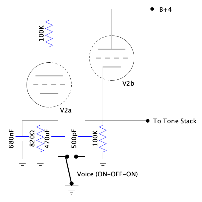
- The Circuit: V2a operates with its standard 820Ω cathode resistor bypassed by a 680nF (0.68μF) capacitor. V2b has no snubber capacitor.
- The Effect: The 0.68μF capacitor is a classic Marshall value. It boosts upper-mids and highs while keeping the bass tight to prevent a “muddy” or “farty” low-end under high gain.
- Frequencies Affected: The boost starts around ~430 Hz.
- The Circuit: Connects a massive 470μF capacitor in parallel with the V2a 0.68μF capacitor.
- The Effect: This effectively bypasses the 820Ω resistor for all audible frequencies. This dramatically increases the gain of the lower frequencies.
- Frequencies Affected: The -3dB cutoff point drops to < 1 Hz. This introduces a massive amount of low-end chunk and overall gain, making the amp sound much fatter and more vintage, though potentially looser on palm mutes.
- The Circuit: Leaves V2a in its default (tight) state, but connects a 500pF capacitor from the V2b cathode to ground.
- The Effect: Tames the aggressive clipping of the cathode follower.
- Frequencies Affected: Using the formula f = 1 / (2πRC), during tube cutoff (R = 100kΩ), this creates a high-cut filter starting at roughly 3.18 kHz. This rolls off the “ice-pick” highs and upper-order fizzy harmonics, making the overdrive sound creamier and more modern.
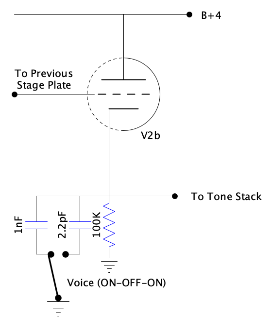
- The Circuit: Standard cathode follower driving the tone stack with no capacitors to ground.
- The Effect: The brightest, most aggressive, and most open setting. Maximum high-end “bite” and Marshall-style crunch.
- The Circuit: Connects a 1nF (1000pF) capacitor to ground.
- The Effect: A more aggressive version of the smoothing effect seen in Variation 1. It cuts out the harsh upper-fizz while retaining most of the upper-midrange bite.
- Frequencies Affected: Cuts frequencies above roughly 1.59 kHz during clipping.
- The Circuit: Connects a larger 2.2nF capacitor to ground.
- The Effect: A heavy blanket on the high-end. This creates a very dark, heavily compressed, “liquid” lead tone often associated with modern high-gain boutique amps.
- Frequencies Affected: Cuts frequencies above roughly 723 Hz during clipping. This significantly rounds off the attack and removes almost all presence-range fizz.
130 ohms: The Classic “Pink Taco” Compromise
150 ohms: The Safe and Punchy Bias
My Mods
Naturally, I couldn’t just build a straight-up clone of the Friedman, but I also couldn’t just follow the kit to the letter. So, here are the custom tweaks I threw into the mix:
LND150 Boosted Input
The PI18 kit comes stock with high and low sensitivity inputs. I re-wired one of them to match the stock PT20 V2 input, and used the other jack hole to install an LND150 solid-state boost mounted right on the jack. The circuit is based on the Headfirst boost, effectively transforming this amp into a Hairy Pink Taco! 🙂 On the bigger BE models, the legendary HBE (Hairy Brown Eye) channel utilizes an extra tube gain stage to accomplish this exact same thing. It hits the rest of the circuit a whole lot harder, totally removing the need for an external overdrive or boost pedal when you want to dial in those crushing, modern high-gain tones.
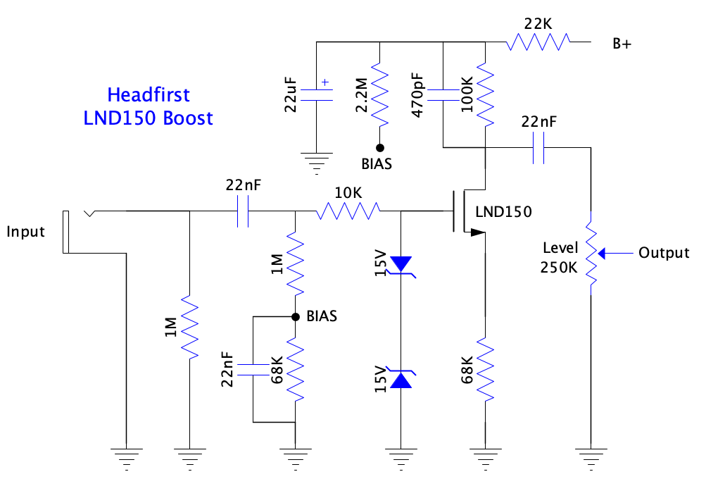
I used a small PCB from Tube-Town for the boost, and even though it isn’t specifically laid out for the Headfirst circuit, it’s nothing a little DIY ingenuity couldn’t fix. With some creative component placement and one resistor tucked onto the underside of the board, it fits and functions perfectly. The schematic below matches the Tube-Town board revision 1.3b and I added notes that explain how to convert it to the Headfirst circuit.
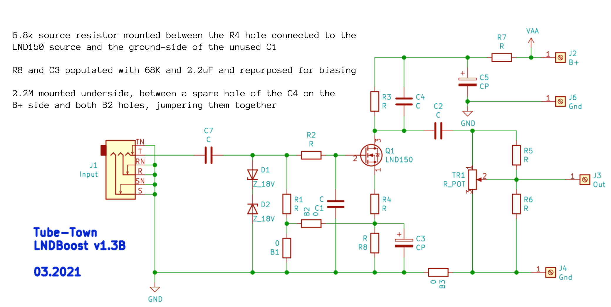
It’s worth noting that the Tube-Town PCB is designed to accommodate several variations of the boost circuit and allows for a decent amount of experimentation. However, the Headfirst circuit uses a brilliant trick: tapping the B+ line to lift the gate and bias the FET, which gives the stage significantly more headroom. This is absolutely crucial if you’re running high-output pickups. A standard cathode-biased LND150 stage has pretty modest headroom on its own, and hot pickups will easily push it into nasty clipping before it even hits the first tube stage.
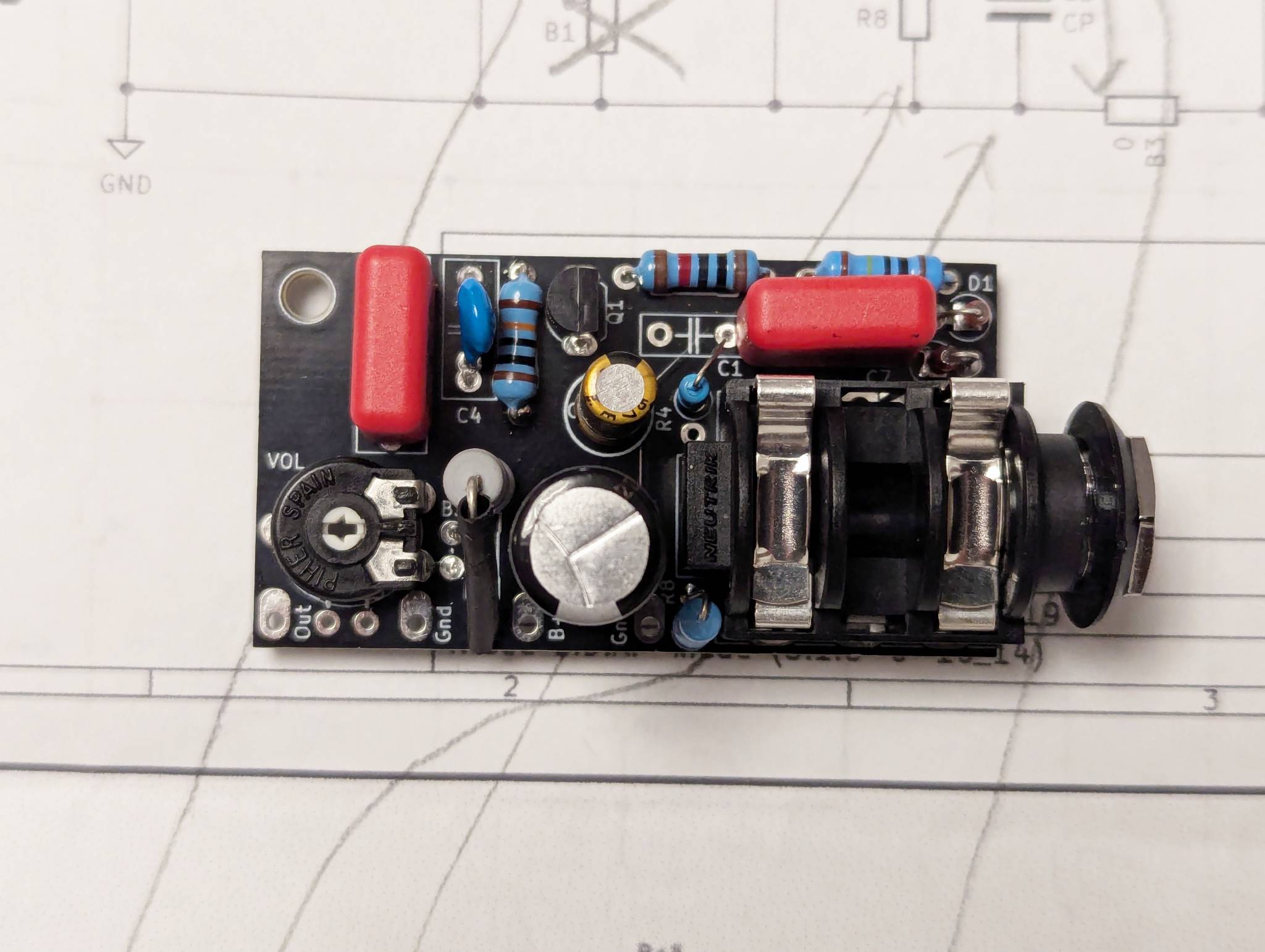
Note the placement of the source resistor tucked between R4 and C1 in the photo above, and that underside bias supply resistor in the photo below. It’s also worth talking about the boost level control. The PCB is flexible enough to let you install either a board-mounted trim pot or a standard panel-mount potentiometer. For the sake of simplicity and keeping the control layout clean, I opted for the trimmer and dialed the level back relatively low—around the 10 o’clock position. This sets the output gain factor to right around 5 (or a little less), which is honestly more than enough juice. The LND150 is capable of pushing way more gain than that, but pushing it too hard completely kills the dynamics and turns your guitar signal into oversaturated mush. I verified gain levels on the oscilloscope and made sure that the output is clean.
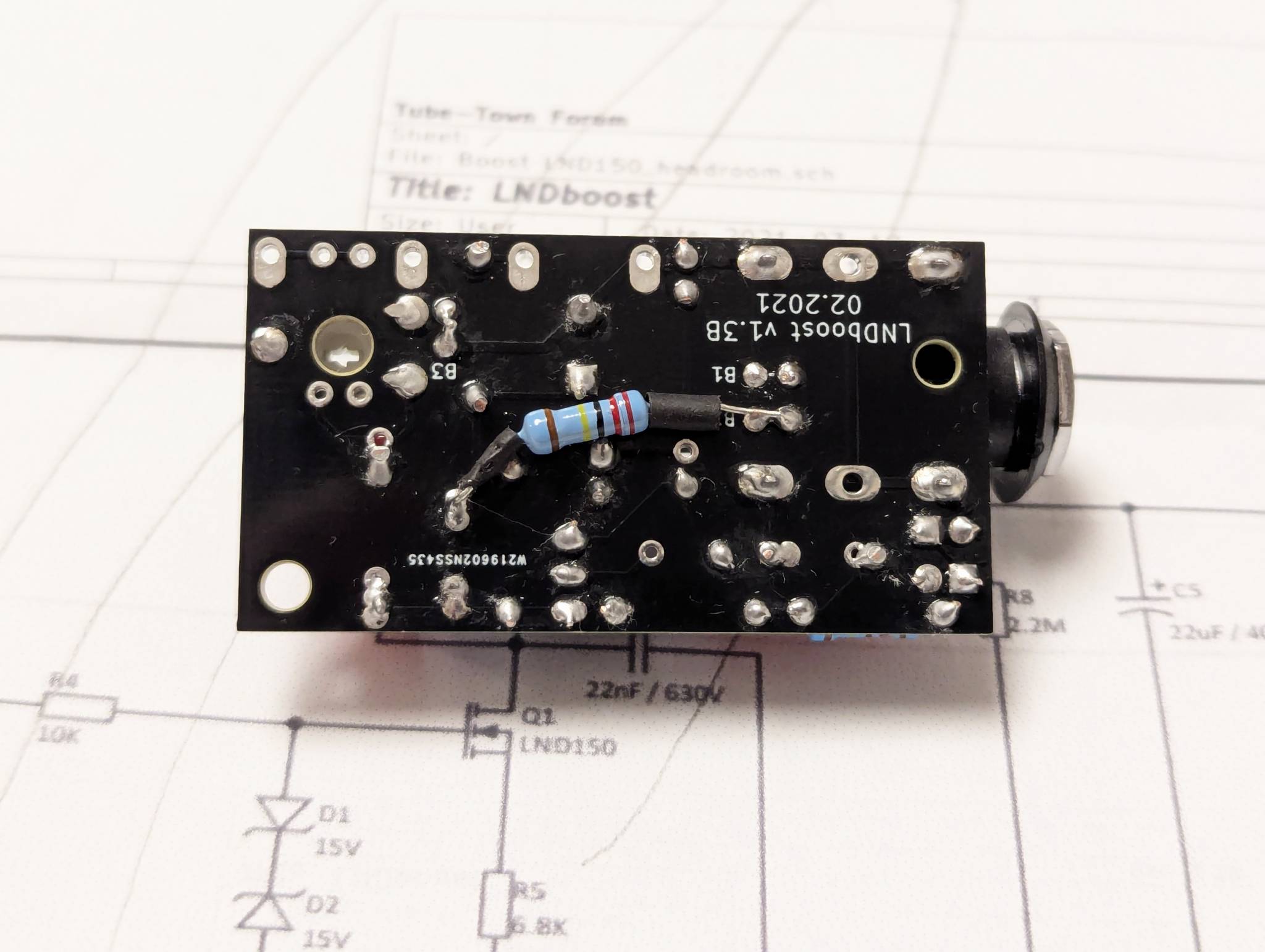
The massive advantage of the Tube-Town PCB is its small footprint—it’s compact enough to mount directly onto the input jack, making for a super clean, drop-in solution. The only minor downside is that space is at a premium for a few of the components, particularly the high-voltage filter cap. I could only squeeze in a 4.7μF 450V capacitor, as a 10μF body was just too big to fit the board. Luckily, even at 4.7μF, paired up with that 22K series resistor, it provides more than enough filtering to decouple the boost’s power supply from the rest of the amp’s circuit and keep things quiet.
Switchable NFB
I just couldn’t bring myself to give up the raw, wide-open roar of the original non-NFB circuit, so I added a toggle switch on the rear panel that lets me completely defeat the negative feedback loop whenever I want that extra aggression. This is easy enough to do and only requires a toggle switch mounted near the impedance selector as that’s where all OT secondary leads are terminated.
Bright Pull Switch
My main goal with this build was to cover pretty much everything I love to play, and that includes a massive dose of Ritchie Blackmore. His early Deep Purple tone was actually fairly clean, but it was incredibly tight, punchy, and bright. Because of that, being able to back off the gain and still dial in a crystal-clear, snappy rock tone was incredibly important to me.
To get there, I repurposed the push-pull pot for a switchable bright mode that runs a 4.7nF capacitor in series with a 220K resistor right across the gain pot. Unlike a standard, simple bright cap that can sound incredibly shrill when the gain is rolled down, this network sounds much smoother to my ears. The cap value is much larger than what you’d normally see, which lets a wider range of frequencies pass through, while the series resistor limits the overall intensity of the effect. The result is a gorgeous top-end clarity that adds brightness and bite without making the amp sound thin.
Regulated DC Heater Supply
I absolutely despise background noise (honestly, who doesn’t?), and I’m always looking for ways to push the noise floor down as low as humanly possible. The stock PI18 kit uses AC heaters elevated to about 55VDC, and the heater transformer winding is center-tapped—which is pretty much the gold standard for an AC heater setup. But I wanted to take things a step further. I kept that elevated AC setup for the phase inverter and the two power tubes, but decided to implement a dedicated DC heater supply for the first two preamp tubes. Those first two bottles handle the vast majority of the preamp gain, meaning any stray noise or hum introduced there will get amplified over and over down the line.
Luckily, the PI18 kit ships with a fantastic “EXT” version of the classic 18W Marshall power transformer, which comes packed with the following windings:
Those last two windings are normally left completely unused in the standard PI18 build, but they gave me a killer idea. When wired up in series—making sure to mind the phase of each secondary—they provide more than enough raw voltage to feed a voltage regulator. This allowed me to build a rock-solid, super-clean 12.6VDC supply capable of easily delivering the 300mA needed for those first two preamp tubes.
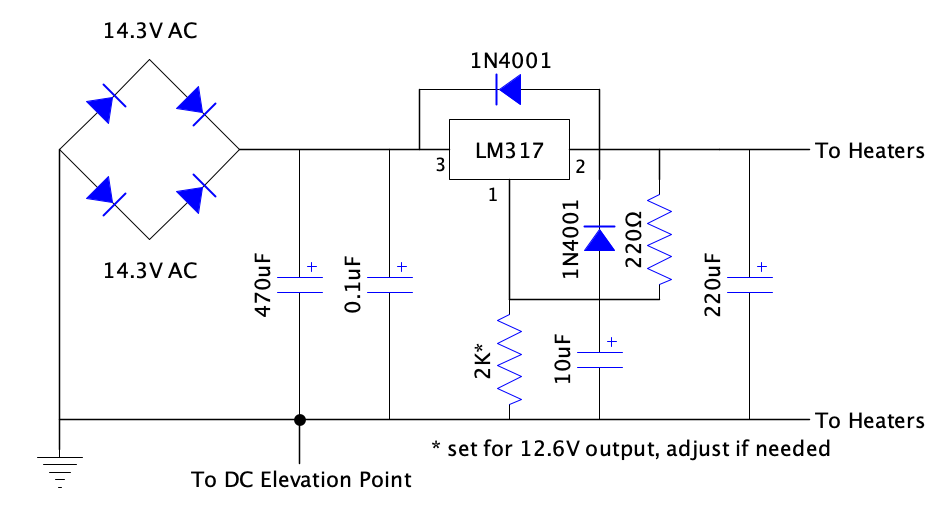
For the circuit, I grabbed a trusty LM317 adjustable linear regulator and dialed it in to output exactly 12.6VDC. The circuit layout is straight out of the datasheet. The beauty of using a regulator here is that you don’t need a massive, bulky bank of filtering capacitors like you would with a passive, unregulated DC supply. The LM317 does an incredible job of wiping out AC ripple all on its own, provided you feed it enough raw input voltage to stay comfortably above your target output plus the few volts of headroom the regulator requires to do its thing. My scope was showing less than 10mV of ripple under full load.
To lay down the regulation circuit, I used small, eyelet-style prototyping boards from Banzai Music. They feature two rows of six plated-through holes and are absolutely perfect for building compact helper boards and sub-circuits. That said, I was definitely pushing the envelope trying to pack this entire layout onto one. It got a bit crowded around the LM317 regulator pins, but with a little patience and careful lead clipping, it all went together securely.
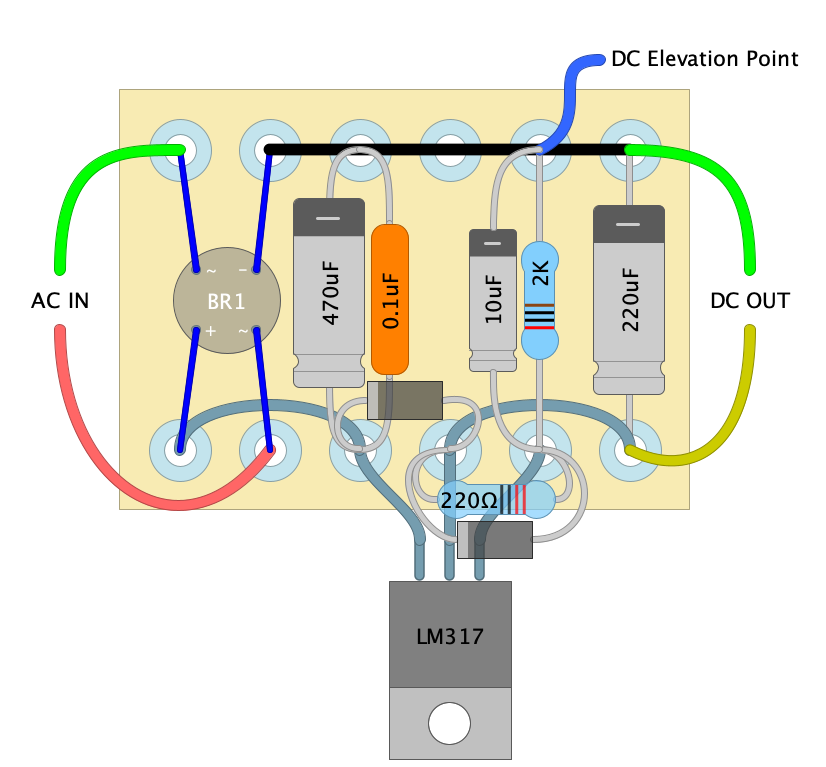
But all that sweet regulation comes at a cost: heat that we have to dissipate somehow. At a 300mA load, we are wasting a couple of watts. That might not sound like a ton on paper, but without proper management, it will quickly push the regulator up to 125°C and send it straight into thermal shutdown. To keep things running cool, I bolted the regulator directly to the aluminum chassis, using the entire enclosure as a massive heatsink. Of course, because the metal tab on an LM317 is tied internally to the output voltage, you can’t just bolt it directly to a grounded chassis without causing a dead short. To solve this, I used a silicone thermal pad and an insulating nylon shoulder washer with a nut and bolt to securely isolate it from the chassis while still letting the heat transfer beautifully.
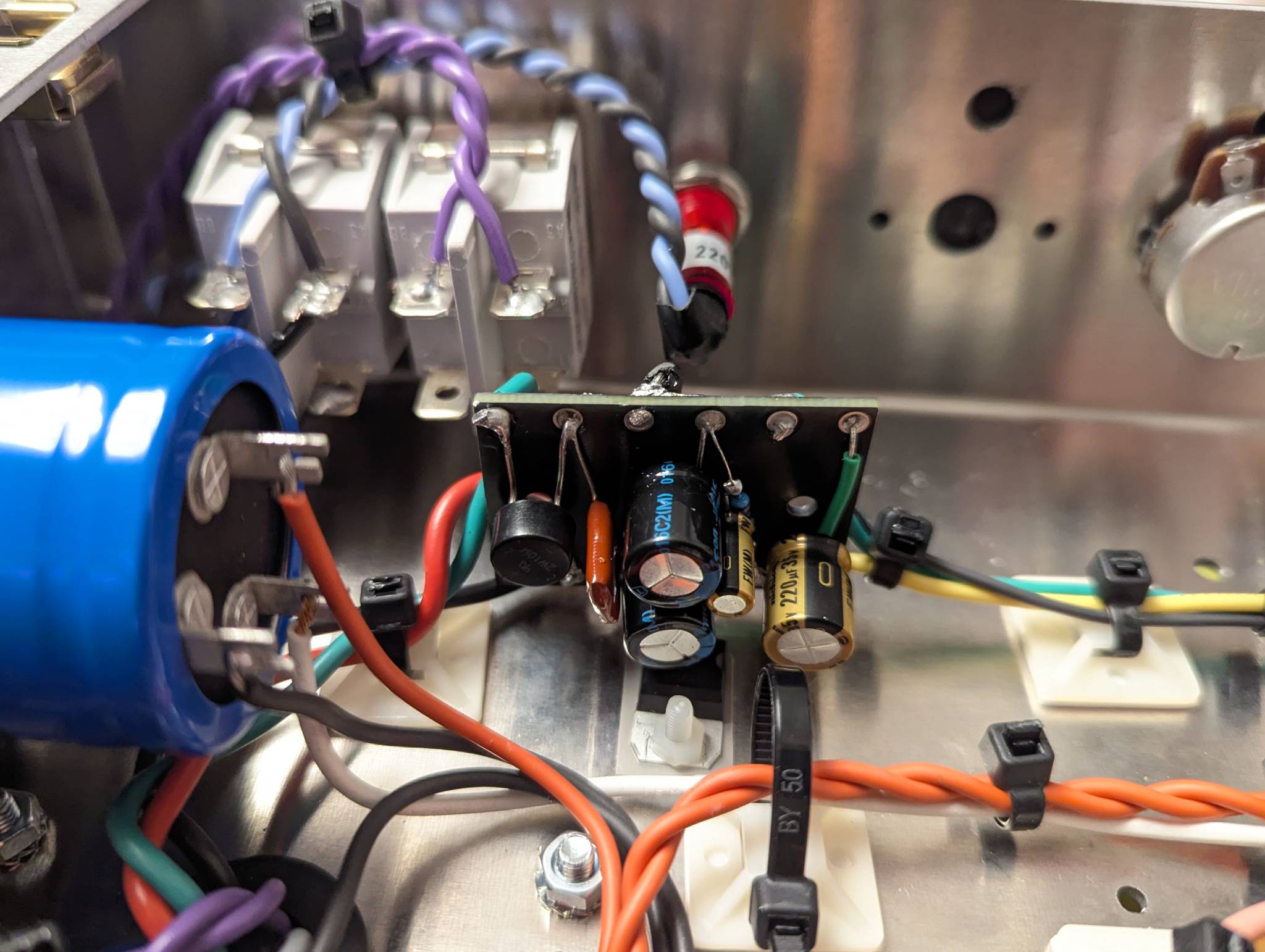
Since I already had that 55VDC elevation reference circuit hooked up for the main AC heater line, I tied the new DC heater supply into it as well. This keeps the heater-to-cathode voltage safely reference-elevated, which is cheap insurance for protecting the tube insulation on that hard-working cathode follower stage.
Build Journal
This is actually my first time building an amp from a kit, and while it’s still a challenging project, having everything pre-packaged makes life a whole lot easier. For starters, it completely spared me from doing heavy chassis metalwork, which is a part of the building process I’ve never particularly enjoyed (aside from drilling a few extra holes for my mods, of course!). Also, even though there’s no hand-holding step-by-step manual included—just the schematic and the layout diagram—having a tried-and-tested PCB and wiring layout simplifies things immensely. Normally, I’d be designing the eyelet board from scratch and mapping out the entire chassis layout myself, just crossing my fingers that I planned everything right. The kit takes all that guesswork away.
That said, it’s still a highly demanding build, and I really took my time with it—stretching it out over nearly a month of late-night sessions with the soldering iron. I gave it my absolute best to keep the lead dress and wiring as pristine as possible, which took a mountain of patience. On some nights, I’d only manage to run a couple of wires before calling it a day, but the end result was completely worth the effort.
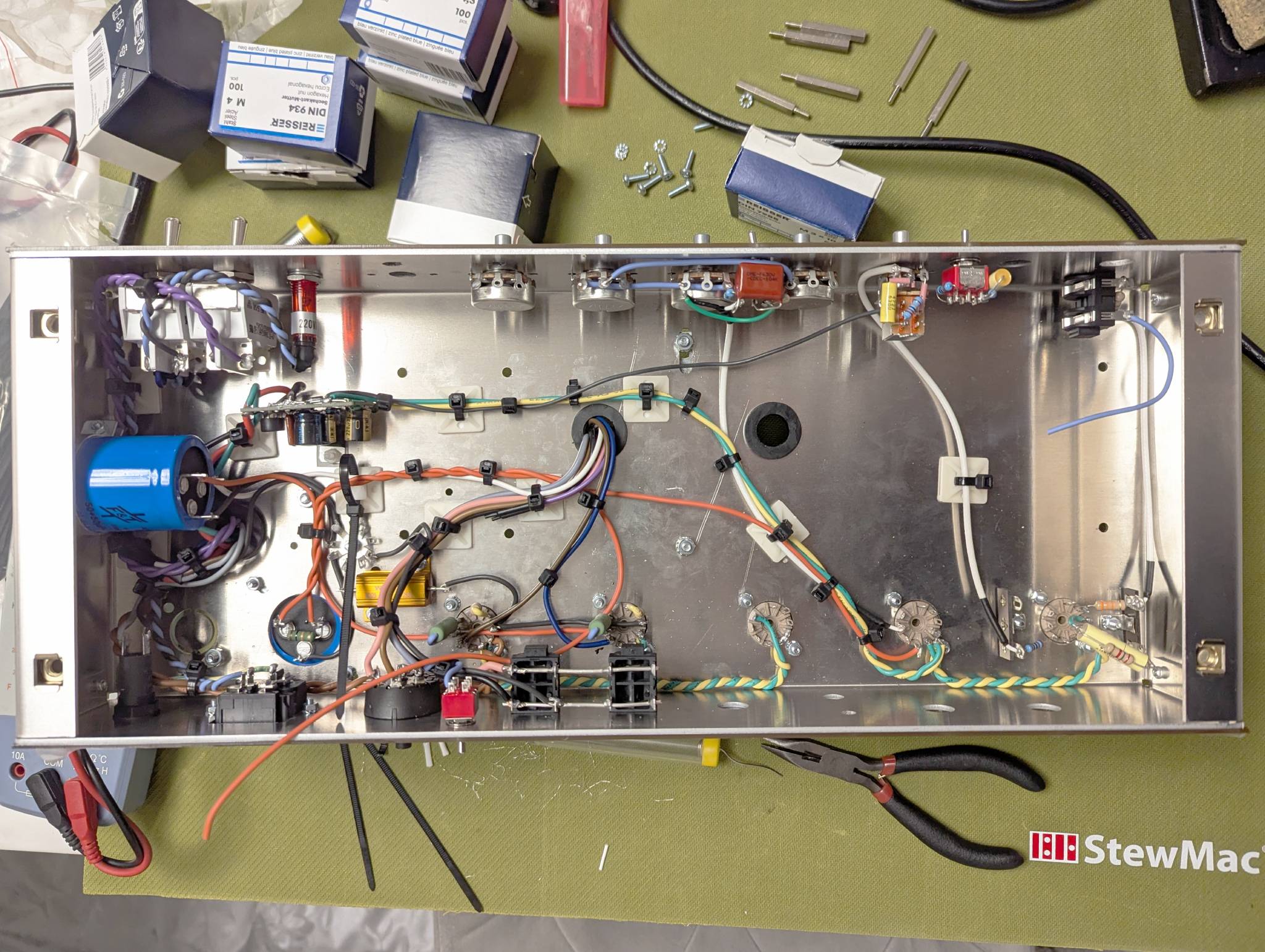
The photo above shows the state of the chassis wiring right before I dropped in the main PCB, the booster board, and the FX loop. All the AC lines coming off the power transformer are tightly twisted together and routed as far to the left as possible to minimize hum. The only exception is the main heater wire pair running along the back corner of the chassis to feed V3, V4, and V5. Every longer run carrying an audio signal is fully shielded. For the layout, I used a combination of Teflon RG-174—which is a bit stiffer and holds its shape nicely for runs between chassis-mounted pots and jacks—and the standard PVC RG-174 that came with the kit for the runs heading to and from the PCB.
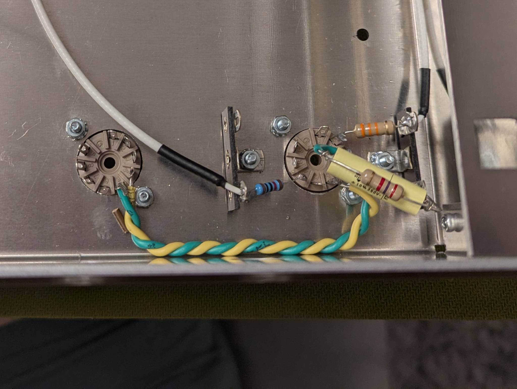
The photo below shows the V1 wiring in much greater detail. Nailing the layout around V1 is absolutely crucial for taming the overall noise floor, since any stray hum or interference introduced this early in the circuit gets amplified over and over again by the subsequent gain stages. Notice that both grid resistors are mounted directly onto the tube socket using tag strips. Even though the PCB has a dedicated spot for the first stage’s grid resistor, I decided to skip it. There was a spare lug on the tag strip anyway, and keeping that grid resistor tucked as close to the socket pins as possible is always the best strategy for killing radio interference and noise. You can also see the first stage’s cathode resistor and bypass cap mounted in the exact same fashion. Interestingly, the stock PI18 kit is designed to have the second stage’s cathode RC network sitting on the socket, but I flipped things around. Because the V2 circuit adds the structure switch to that second stage, it was way cleaner and more optimal to run those connections straight from the PCB instead.
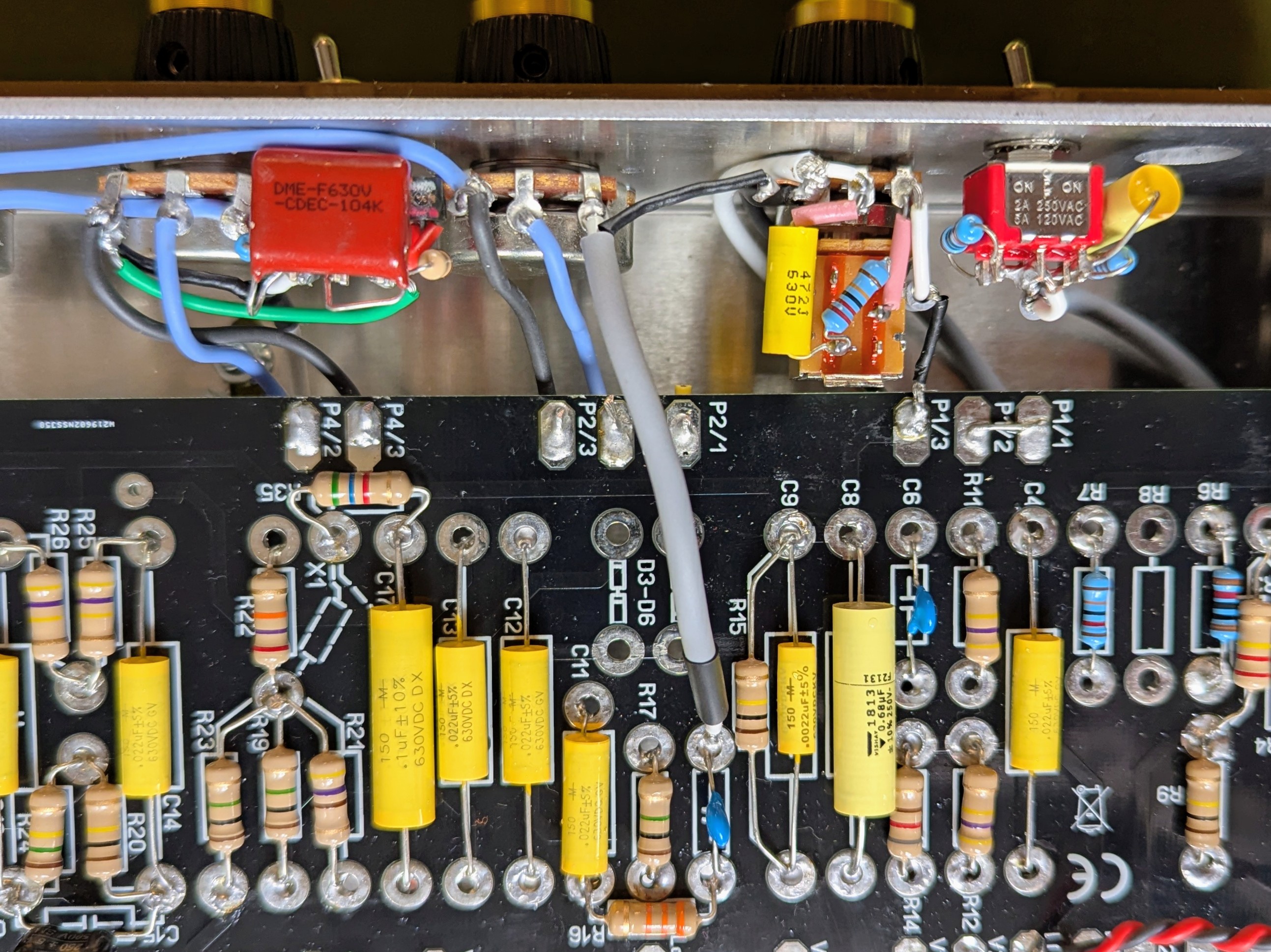
The photo below shows the wiring around the gain pot with the main PCB finally dropped into place. In hindsight, I probably could have placed the structure switch a bit further to the right to give the gain pot some extra breathing room. But for some reason, I was dead-set on keeping it in the exact same relative spot as the original PT20 V2—completely ignoring the fact that I had packed a whole family of components directly onto that switch! Luckily, the tight squeeze didn’t introduce any extra noise or crosstalk from being so close to the gain pot. However I was getting some high pitched squeal and chopstick method revealed that the lead between the P2/1 pad on the board and the input of the Treble pot was sensitive to noise and introduced oscillations. Instead of it I used a shielded lead going straight from the output of the treble capacitor to the input of the Treble pot and the oscillations were gone.
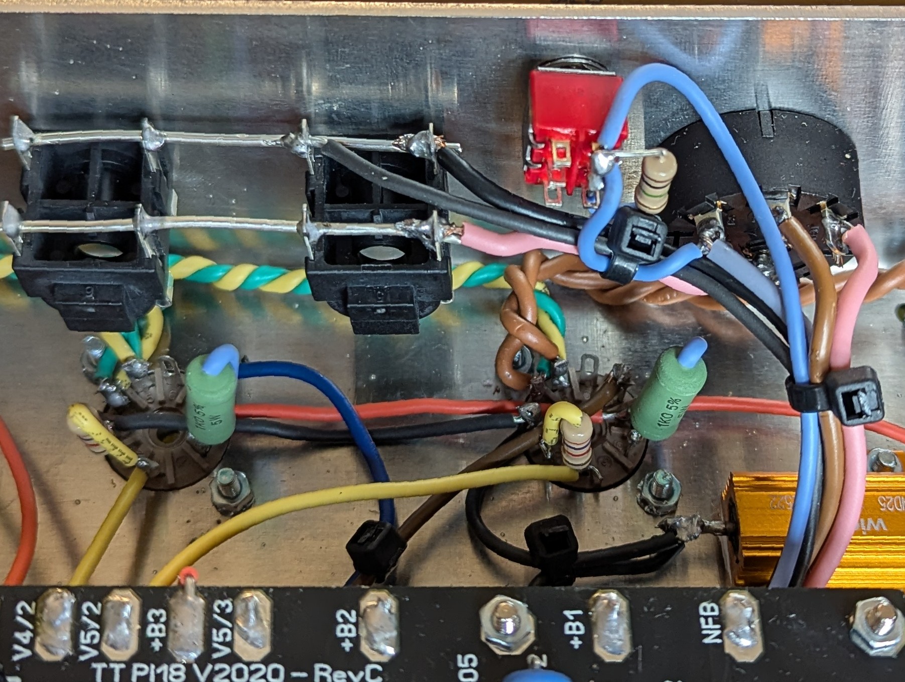
The output tube wiring reveals direct-mounted grid resistors as well as screen resistors mounted right at the sockets. It also shows how things are mapped out around the speaker output jacks. I placed the NFB toggle switch right next to the impedance selector and tied it directly into the 16-ohm transformer tap. Originally, hitting that switch introduced a pretty loud pop when engaged. To cure that, I threw a 1M resistor across the switch terminals. This keeps the negative feedback loop technically connected at all times, but in the “disengaged” position, that massive 1M resistance makes the feedback current negligible. Most importantly, it keeps the circuit references stable and completely stops the popping. Naturally, flipping the NFB toggle makes a massive difference in output volume, since negative feedback reduces the overall level drastically while making the sound a bit cleaner and wider. It’s definitely worth having both options on tap. Another great alternative would be using a potentiometer instead of a toggle switch, which would allow you to continuously dial in the exact amount of NFB being fed back to the phase inverter.
SAT switch was particularly tricky to fit between the Treble and Middle pots. I was contemplating rotating them for 180 degrees, so that the lugs are facing down, leaving plenty of room for the switch, but since there was no noise caused by the proximity, I left it alone.
In order to fully integrate the mods into the design and not make them look like an afterthought, I modified the faceplate as well to include the labels for the new switches. Tube-Town faceplate is made from a transparent plastic material that is covered with gold foil from the back, to protect it from scratches. The design was laser engraved from the back and then filled with black paint. I followed the same procedure and used the same font to etch labels for all the switches. As a result, they blend the design perfectly.
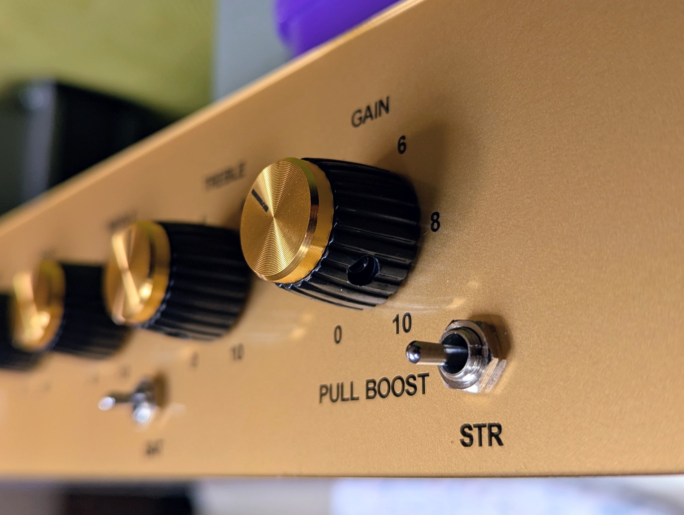
The FX Loop build went together pretty smoothly. The kit generously supplies the components needed to build either a “fat” or “tight” variation of the circuit. I opted for the “fat” version, figuring that the preamp section is already aggressively taming any excess low-end that might otherwise contribute to a flabby tone, and I definitely didn’t want to risk thinning out the amp’s overall bass punch. I used 0.47uF WIMA caps for all four coupling caps, avoiding the supplied 1uF electrolytic capacitor in the C2 position, as it shouldn’t make any audible difference in the low end response anyways.
When it came to tying it into the main circuit, I initially stuck with standard unshielded hookup wire just to keep things simple. I made sure to carefully route those leads as far away as possible from any potential sources of noise or crosstalk, fully prepared to rip them out and swap in shielded cable if the loop introduced any unwanted hum when engaged. Luckily it didn’t come to that.
The suggested 1:22 input voltage divider ratio felt a bit too drastic, as it practically required dimming both the send and return pots just to get back to unity gain. To solve this, I soldered a 1M resistor in parallel with the existing 2.2M series resistor. This brought the divider ratio down to roughly 1:8, which opened up a much more comfortable amount of headroom and allowed both the send and return controls to sit happily right around the noon position for unity gain. Crucially, this tweak preserves the amp’s dynamic feel and avoids introducing unnecessary noise, which often happens when you severely choke a signal down only to aggressively boost it back up on the recovery side.
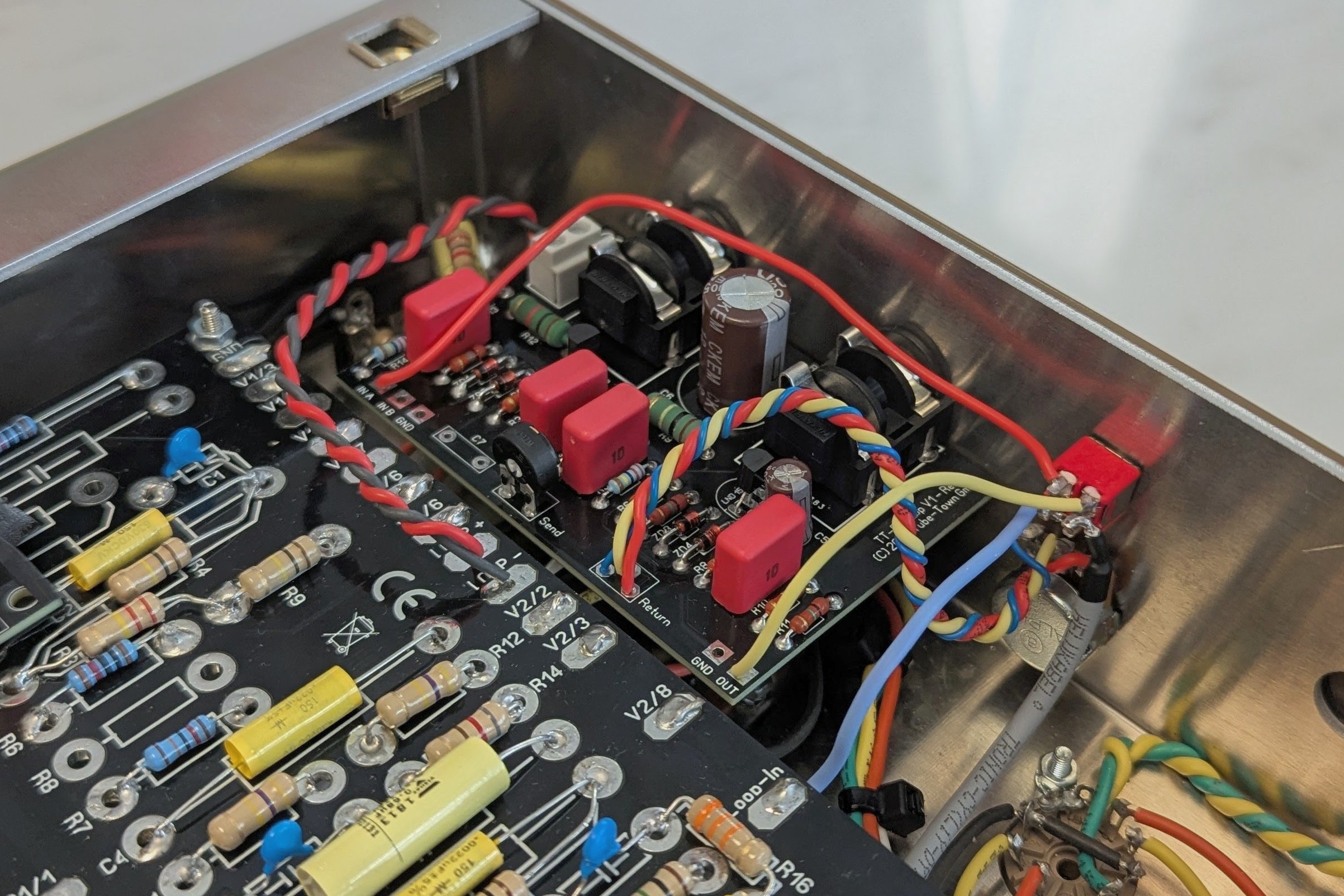
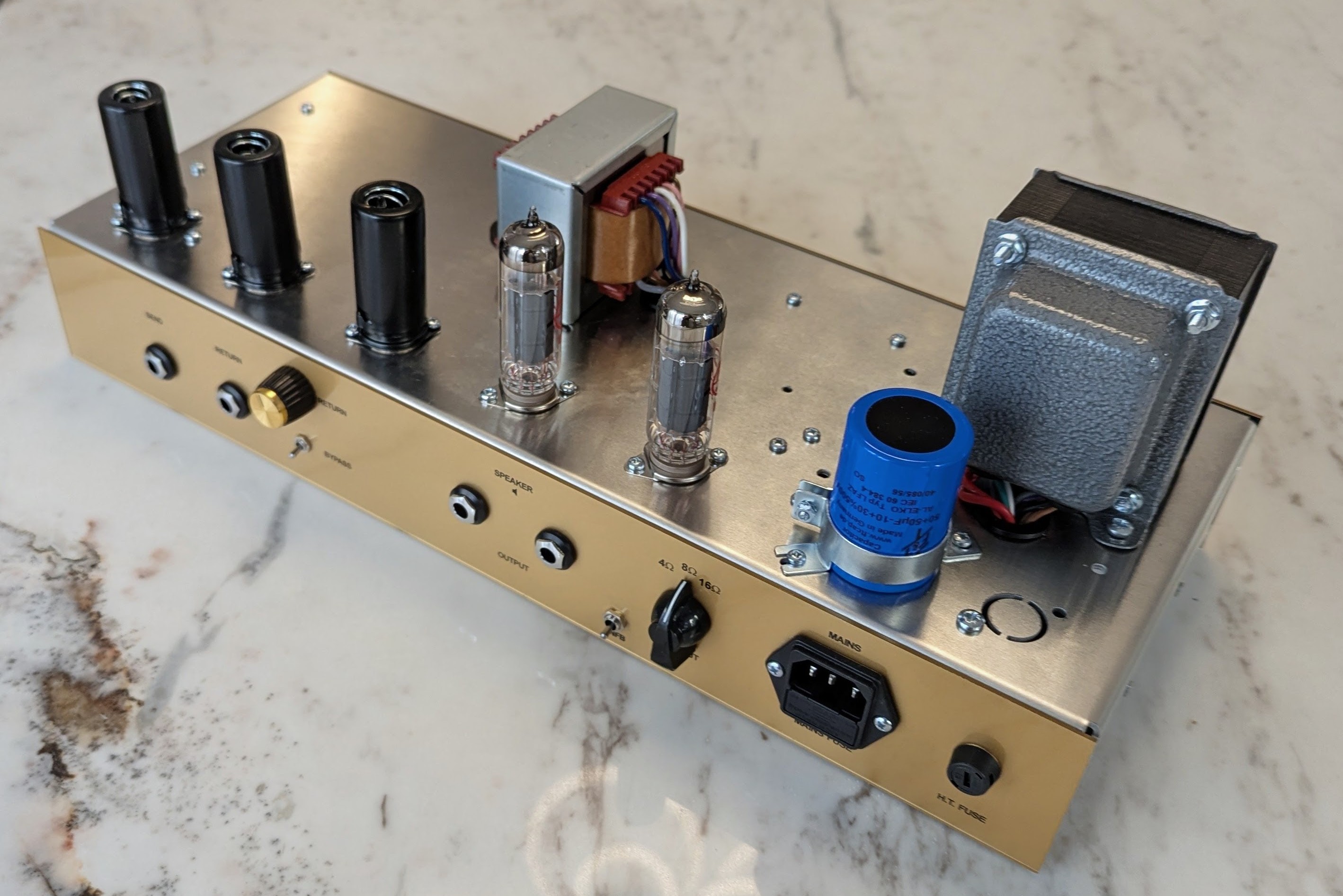
With all the wiring done and all daughter boards installed, this is the finished product.
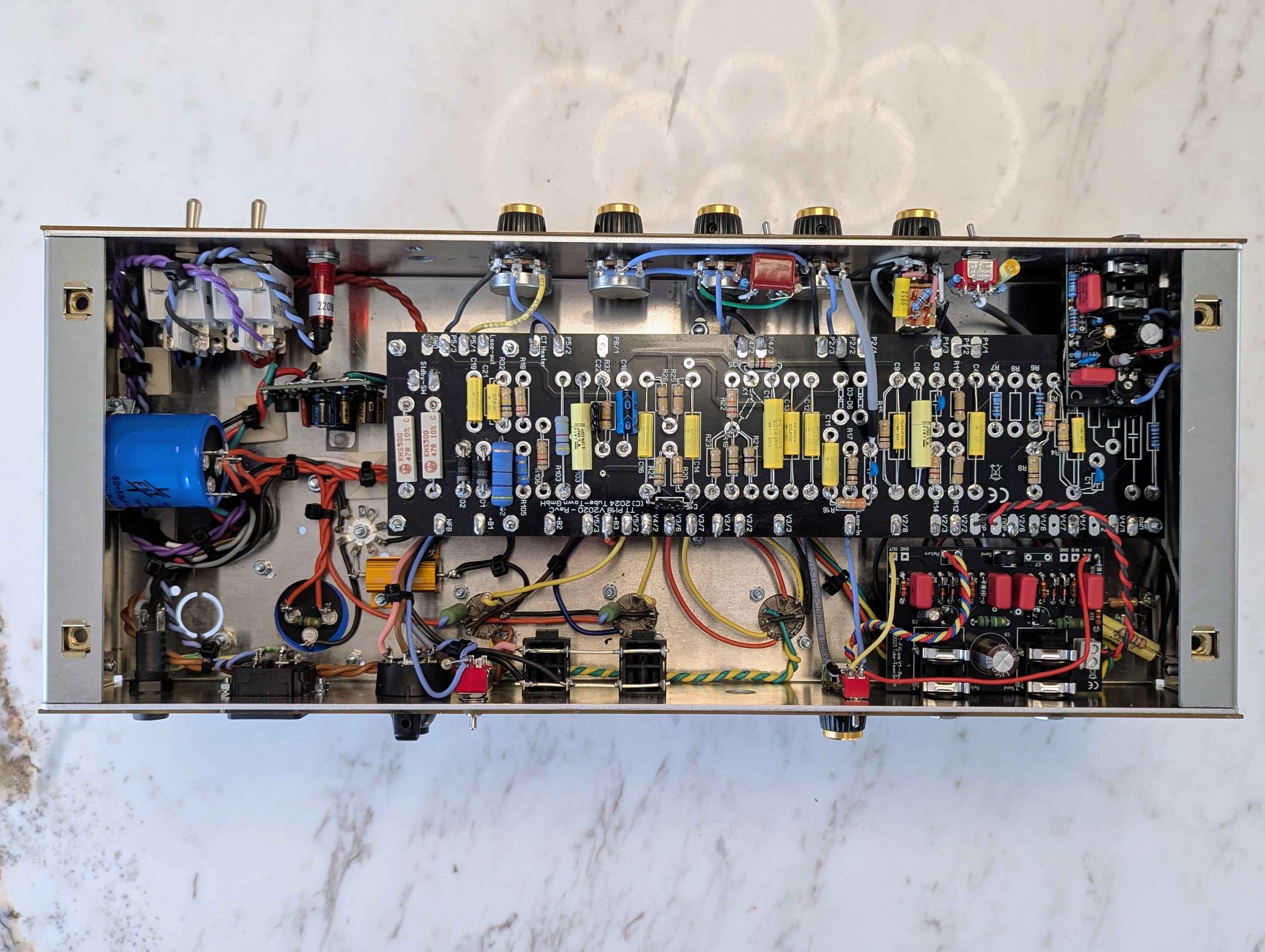
Photos below show the complete chassis with tubes and faceplates installed, waiting for the headshell to be complete.
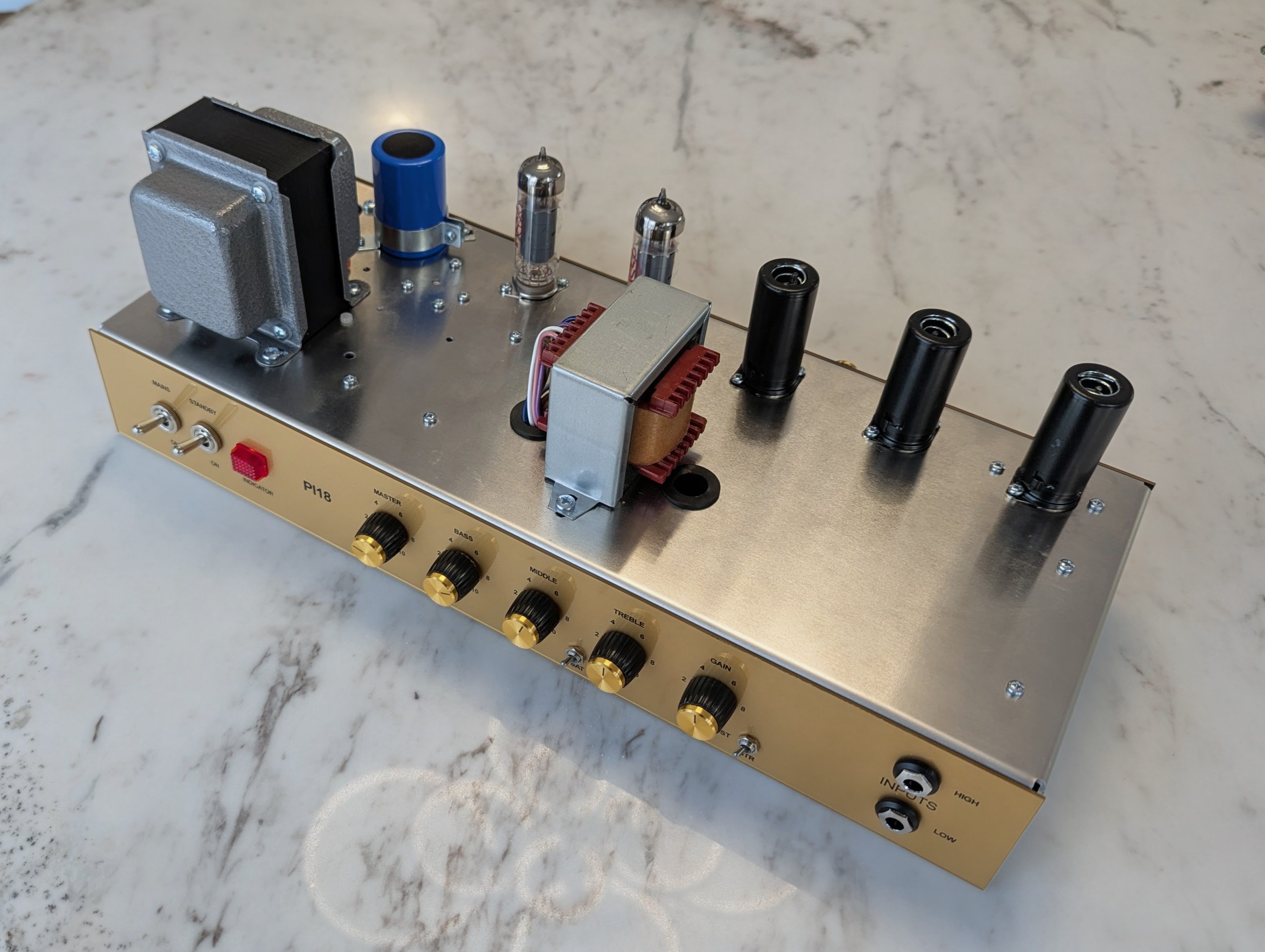
Note the newly added NFB switch next to the impedance switch.
For the headshell I wanted to do something unique, something modern but with a dash of retro, matching the character of the amp. For the sake of simplicity, I commissioned a raw ash box to be built by a local furniture company. Then I applied a CNC design to the front and back cover and stained it with black StewMac stain mixed with water and clear-coated the entire thing in matte PU lacquer.
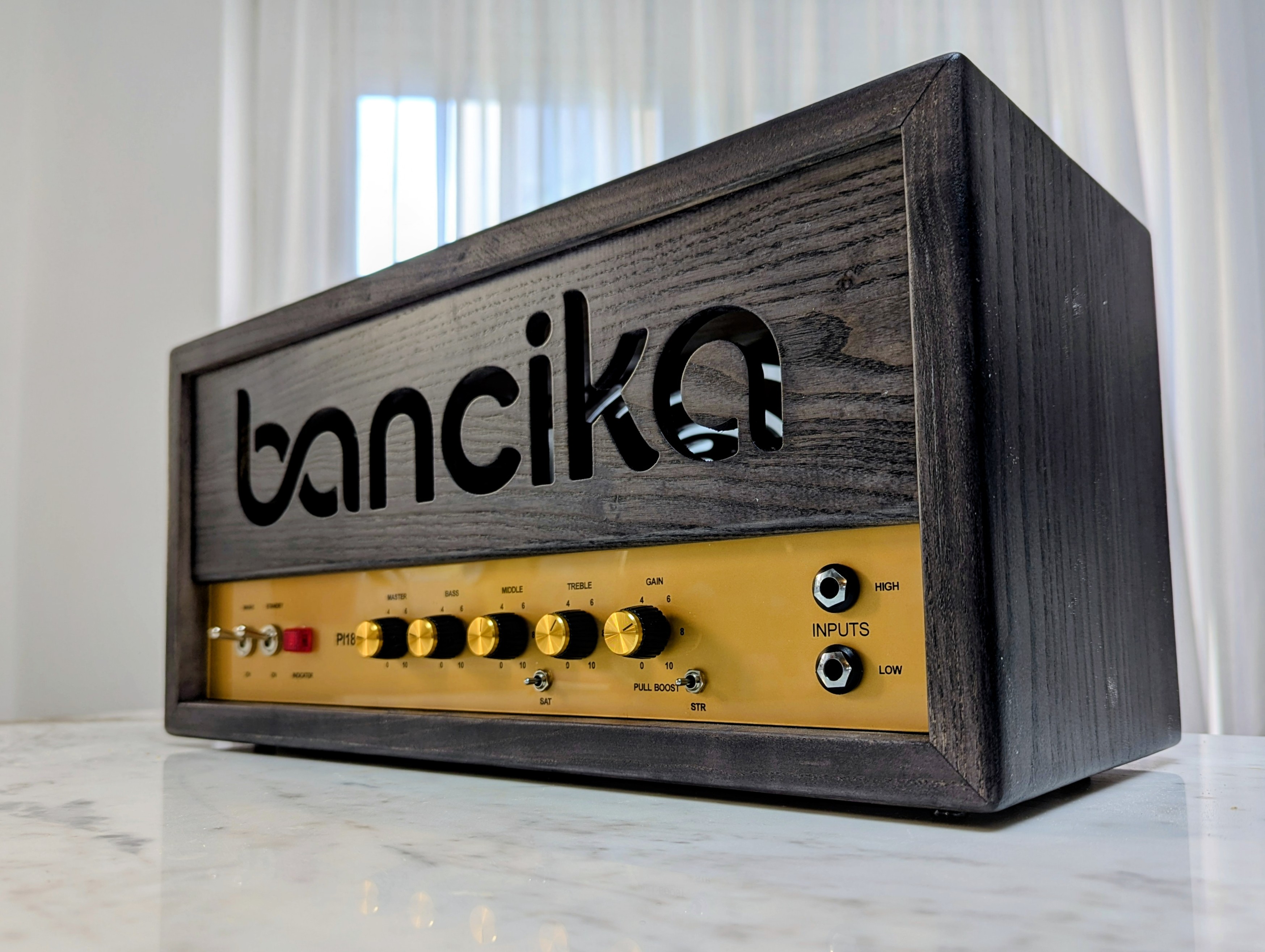
The results are pretty good. The black stain is dark enough and matches the gold faceplate nicely, but still allows the natural ash grain to show through. The matte finish gives it a nice low-key effect.
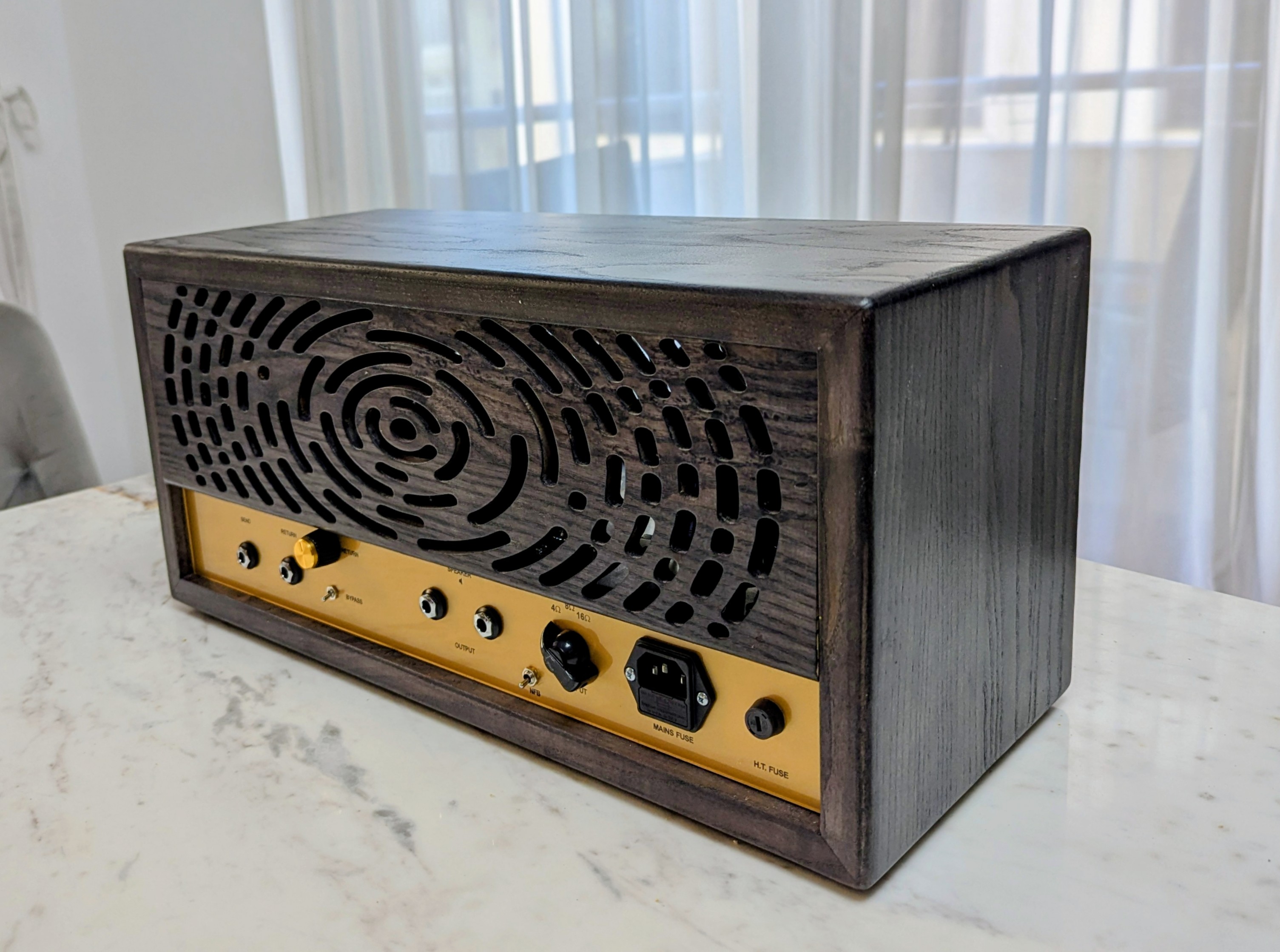
The back cover is held in place with small but strong 8x3mm neodymium magnets in each corner so it can be removed easily for service access. I opted for a heavily vented design to allow some ventilation and get the heat generated by the tubes out.
Tube-Town PI18 Kit Review
TL;DR: The PI18 kit is a fantastic way to build either the V1 or V2 (with a little tinkering) of the Pink Taco, provided you already know your way around a tube amp. It serves as a well-thought-out platform that saves a massive amount of time and effort on layout planning, chassis drilling, and board fabrication. It isn’t absolutely perfect, and there are a few design choices I’d tweak, but overall, it comes highly recommended.
Pros
Cons
Other Friedman Mods
During the preparation stage of the build, I did a homework on most (if not all) the popular mods Friedman performs on Marshalls and includes on his own amps as a way to add more versatility and considered including them in my build. We already mentioned Structure, Saturation and Fat switch, but there are are some more. I ultimately decided not to include them, but they are worth mentioning.
C45 Switch
The C45 mod can be found as a stock feature on certain Friedman BE models, but it actually originated as a classic Marshall mod. In essence, it isn’t too far off from the Tube-Town “Boost” switch, just a bit more elaborate. It is typically inserted between the first two gain stages, where it manipulates the interstage voltage divider to shape both the overall gain level and the top-end response. Let’s dig into the schematic.
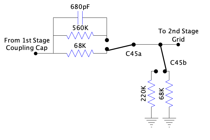
The DPDT ON-ON switch functions as follows:
While the overall gain for the lows and mids drops to roughly 28% in Position 2, the 680pF parallel capacitor completely changes the game for the top end. It acts as a treble bypass (often called a “peaker” network), creating a high-pass shelving filter that drastically revoices the amplifier.
The Tonal Effect: When switching from Position 1 to Position 2, you are intentionally stripping away the heavy low-end frequencies that can easily choke a high-gain circuit. Meanwhile, everything above 1.48 kHz is allowed to hit the next gain stage completely unattenuated. The result is an incredibly tight, aggressive, and “bitey” response. If you’re building a high-gain circuit designed to push hot humbuckers through a dense mix, this switch is the perfect tool for instantly tightening up the tracking and adding clarity.
Given that the PT20 already features a gain pot between those first two stages—and considering I’ve already included a switchable treble bleed circuit in my build—there really isn’t any practical reason to implement the C45 mod here.
Voice Switch
Voice switch is another cool mod that I considered but ultimately didn’t implement for the sake of relative simplicity (it’s a complex build even without it). I came across two different variations of the mod and will take a deep dive into both.
BE 100 Variation
This variation is highly versatile because it addresses two entirely different stages of the amplifier depending on the switch position.
Center Position (OFF / Default)
Left Position (ON / “Fat” or “Thick” Mode)
Right Position (ON / “Smooth” Mode)
BE 50 Deluxe Variation
This variation ignores the V2a gain stage entirely and focuses strictly on tailoring the high-frequency response of the V2b cathode follower clipping.
Center Position (OFF / Default)
Left Position (ON / “Smooth” Mode)
Right Position (ON / “Dark” or “Creamy” Mode)


![John Petrucci - State of Grace [Guitar Cover]](https://i.ytimg.com/vi/K3bYjMICR5g/default.jpg "John Petrucci - State of Grace [Guitar Cover]")

